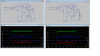
I ran several simulations using the diagram in 13, pn transistors, and again with a FET and both gave approximately the same square wave with the same current rise time, but the quickest current decay was with 3 1000v, 6a diodes in series with the inductor, 160 μs, with 2, 165 μs, with 1, 172μs, worst was with a shunt diode, decay was as slow as build up. A snubber appeared to be good, reduced the oscillating.
Time starts at .1ms, Current flat lined at 4.43A after 4.211ms, at .2ms current was 897ms, at .3ms - 1.61A, .4ms - 2.19A, .5ms - 2.64a, .6ms - 3a, .7ms - 3.3a, .8ms - 3.5a, .9ms - 3.7a, 1ms - 3.85a
I'm tired, think I'll go to bed!!
g'nite