Lucky-Luka
Member
Hi all
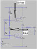
I've read that Sziklai pair are more thermically stable than Darlington ones.
I've read that the influence of the output device is considerably less than that of the driver using the Sziklai configuration.
Unfortunately I haven't really understood what it means...
Happy holidays
I've read that Sziklai pair are more thermically stable than Darlington ones.
I've read that the influence of the output device is considerably less than that of the driver using the Sziklai configuration.
Unfortunately I haven't really understood what it means...
Happy holidays