Continue to Site

Welcome to our site!

Electro Tech is an online community (with over 170,000 members) who enjoy talking about and building electronic circuits, projects and gadgets. To participate you need to register. Registration is free. Click here to register now.

  • Welcome to our site! Electro Tech is an online community (with over 170,000 members) who enjoy talking about and building electronic circuits, projects and gadgets. To participate you need to register. Registration is free. Click here to register now.

Counting rotations

Status
Not open for further replies.
After a quick glance, I see you are right again. I know the counter does move up and down with a 12V + pulse. I will redraw it.

Are you sure? From that how would it know which way it is going?

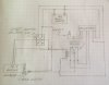
In the diagram in post #34, is your DPDT switch connected correctly? Shouldn't the battery power go to the center terminals?

I think that he means that the counter has two inputs, one for up and one for down, and that each one operates with a +12 V pulse.

The DPDT switch can be wired with the battery to the centre terminals, or the motor to the centre terminals. It doesn't matter which is chosen.
 
Hi SB,
It will work both the way it is shown in the schematic and with tha power feed to the center terminals.

Les.
 
OK: here is the amended sketch.
Actually, when I first played around with rough sketches this is how I had it drawn. I then drew the final version and, I guess, lost sight of the forest for the trees. I did remove the diode.
I am in the process of setting up a little motor that I can test it out on. I will do a video and post it.
 

Attachments

  • F4FEE22C-7853-4C50-9B5E-023E1BD32758.jpeg
    F4FEE22C-7853-4C50-9B5E-023E1BD32758.jpeg
    812 KB · Views: 88
Yes, that’s right. There is two input wires on the counter. A 12+ pulse on one produces an up count and a 12v+ pulse on the other produces a down count.
 
So far so good. I have it set up and running but I haven’t a reed sensor yet. I ordered some online but will take some time to come in.(China)
It seems to work with me running it and opening and closing the two reed sensor wires by hand.
Once I get the reed sensor I’ll post a video.
In the meantime I will work on doing some wiring diagrams to see the least number of wires I need to run from the dash to the downrigger motors and the best way to house it all.
I’m also thinking of using a DPDT relay to operate the motors, allowing for smaller wires to be run front to back.
This may all be for nothing if those up/down Hall effect sensors work the way they say they do. Either way, I will be ready when the ice melts off the bay here.
Again, thanks for all the help! This have been a great learning experience for me. In fact, I am looking into an Arduino or Raspberry Pi kit to see if I can learn a little about microcontrollers, looks like a fun hobby.
 
I got the up/down Hall sensors in the mail yesterday and was able to set up a circuit to try one out.
I don’t think I will be able to use them.
While it does give up down pulses that moves the counter, every time I move the magnet over it, it registers both an up and down count....count stays the same. I have tried every possible distance, angle and magnet placement as well as the speed I move past the sensor. It seems to work one way if I hold it above the magnet and the other if I move it below.....but never up and down. I’m sure I have the sensor oriented in the right direction because it’s marked.
I’m using a small magnet...about 1/4” dia.
I know I am registering up down pulses because little red and green LEDs flash.
I’m going to play with it some more but it doesn’t look good. I think I will be using Diver300’s idea and will try it out when I get the reed switches.
 
Last edited:
I got the up/down Hall sensors in the mail yesterday and was able to set up a circuit to try one out.
I don’t think I will be able to use them.
While it does give up down pulses that moves the counter, every time I move the magnet over it, it registers both an up and down count....count stays the same. I have tried every possible distance, angle and magnet placement as well as the speed I move past the sensor. It seems to work one way if I hold it above the magnet and the other if I move it below.....but never up and down. I’m sure I have the sensor oriented in the right direction because it’s marked.
I’m using a small magnet...about 1/4” dia.
I know I am registering up down pulses because little red and green LEDs flash.
I’m going to play with it some more but it doesn’t look good. I think I will be using Diver300’s idea and will try it out when I get the reed switches.

Try flipping the magnet (s-pole vs n-pole), does it make a difference?
 
Gopher: I did try that but when I do there is no signal whatsoever from the Hall sensor. I think the shielding between the two halves of the sensor is not good enough.
I have no idea how this kind of sensor could ever be used.....I guess that’s why this one is the only one I have ever seen online. Perhaps it’s meant to go along with some electronics to sort out the dual signals.
 
I'm not sure about this, as I can't see any waveforms for that sensor, but it may be that the sensor is for quadrature encoding. (Wiki link)

The idea is that the "up" count will only work if the "up" pulse starts before the "down" pulse, and vice-versa. That function is not usually done inside the sensor, but in the receiving device. The sensor is just two sensors in one housing, close together.

If that is the case, you will get both pulses in each direction. If you move the magnet very slowly, you might see the counter count up then down in one direction, and down then up in the other.

If you do have a sensor like that, you can just use either signal with a relay. There are also electronic circuits that can change quadrature signals to up/down.
 
Diver300: I’m sure you’re correct. I have read about the circuitry that changes the quadrature signal to up down pulses but it’s way over my head. I was hoping the circuitry was built into the sensor itself but I imagine it’s too much to put in the head of a sensor like that.
I think, for my application, using a reed or Hall sensor and the relay to sort out the up down is my best option......seems the simplest. I’m looking forward to getting the reed switch I ordered.
 
Diver300: I’m sure you’re correct. I have read about the circuitry that changes the quadrature signal to up down pulses but it’s way over my head. I was hoping the circuitry was built into the sensor itself but I imagine it’s too much to put in the head of a sensor like that.

The circuitry to convert quadrature to up/down pulses would be tiny, and could easily fit into the sensor. It's not there because the makers don't feel that there is a market for it.

There is nothing to stop you using that sensor. Just have one output connected and use the relay controlled by motor direction to connect that output to either up or down.
 
Of course I can, never thought about it....just use one of the outputs.
Out of curiosity do you feel there’s any advantage using a reed sensor over a Hall? I suspect a reed may be a little more positive but it does have moving parts and contacts....they are rated for millions of close/open cycles, though, and I would be surprised if I used more than a couple of thousand per fishing trip.
Again, I really appreciate the help you’ve given me.
 
All of the satellite dish actuators I have seen just used a reed switch. I have never had any problem using them. An optical sensor or Hall sensor would probably be more reliable in the long term and is more compact. The one thing I have made that is similar to your requirement is a controller for a roller blind uses a reflective opto sensor. When the motor is being driven in one direction the pulses increment a counter. When it is being driven in the other direction it decrements a counter. When the counter reaches the preset value for the up position it stops the motor. The same happens for the down position. I chose this method as it would be difficult to use limit switches with a roller blind.

Les.
 
Les Jones: I guess if a person wanted to set up a downrigger so you could punch in a depth and have the motor turn the appropriate number of rotations to reach that depth, using an incremental encoder is how you would do it. I would have to do a lot of studying before I could do anything like that.
 
I have an Arduino kit on order. I looked at it and Raspberry Pi and decided on the Arduino. Really neat stuff and all “open source”. I worked on a lot of hydraulics, pneumatics and electricity stuff but always found electronics pretty intimidating....time to give it a try.
 
Status
Not open for further replies.

Latest threads

New Articles From Microcontroller Tips

Back
Top