Continue to Site

Welcome to our site!

Electro Tech is an online community (with over 170,000 members) who enjoy talking about and building electronic circuits, projects and gadgets. To participate you need to register. Registration is free. Click here to register now.

  • Welcome to our site! Electro Tech is an online community (with over 170,000 members) who enjoy talking about and building electronic circuits, projects and gadgets. To participate you need to register. Registration is free. Click here to register now.

Counting rotations

Status
Not open for further replies.
Gophers: It’s a mechanical counter just like that, on the downrigger right now and works just fine. The problem is having to leave the boats steering wheel to move the ball up and down. I can’t read the counter from the seat....probably 10 feet away. Since I fish in an area where the bottom is rocky and very undulating I’m up and down a lot to raise and lower it. It’s dangerous if the ball snags on bottom because if the clutch is not set properly it could pull the rear of the boat under. I want to raise and lower it from the drivers seat which is easy but I have to know the depth I’m moving it to.
I have seen some systems online that will do it and even can be hooked up to a depth sounder to automatically keep it a certain distance from bottom. It would be nice to have that but for the price of it I can buy quite a few tons of fish. :)
 
Found this sensor. I have looked at so many sites but never came across this one before. If it works as I read the discription it would be the simplest way yet to count the revolutions. I have no idea how they work, distinguishing up/down, other than thinking there is two Hall sensors built into one unit and it can distinguish which one moves to the magnet first???
https://www.aliexpress.com/item/NJK...481.html?spm=a2g0s.9042311.0.0.4fcc4c4diye9kU
I just ordered two of them, but since these may take up to a month and a half to get to Canada, I’m still going to set up a test circuit based on Diver300’s idea, which I’m sure will work. I’ll keep in touch.
Really appreciate all the help.
Hall sensors can differentiate between magnet polarity so it depends on a properly polarized magnet mounted in the proper orientation to determine direction.
 
That type appears to have two Unipolar hall sensors, you need to orient the head right so that each side registers, one after the other, the two types will offer bi-directional sensing, with the first trigger occurring dependent on direction.
Max.
 
I sure hope it works!! It would simplify so much. There would be so little wiring and components involved.
I understand Hall sensors are not as “positive” as reed sensors, but surely this one is designed for a purpose such as this. I’ll do some experimenting when they get here.
I’m just sitting here on my third cup of ☕
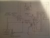
️, drawing a sketch of Diver300’s idea. I think I have it under control......
Thanks. I am learning so much.....I guess you’re never too old.
 
Now on sale for just $7.99.

I paid $14 last time I needed one. I put a small plastic gear on the shaft and used a v-belt pulley for the rope and the plastic gear pressed against the rope as it ran across the pulls (so no load on the plastic gear).

**broken link removed**
.
.

Years ago at work I helped some guys build some downriggers and that is what we used. But then again there was more than one guy in the boat, and while one guy drove another guy controlled the down rigger.
 
Yeah, It’s no problem when I have a buddy in the boat but I’m often alone and usually have two downriggers down. It really keeps me busy. I hate leaving the steering wheel or shutting down the engine because the boat turns all over the place and if I shut the engine down, the lures drop and snag on bottom. I often lash the wheel but it takes time and the bottom really comes up fast in places where I am.
I’m impressed that you built downriggers.
 
Get the little mechanical counter, strap your old Samsung phone above it and turn on the camera. Then turn on screen mirroring and connect to a monitor at the back of the boat.
 
Now, that’s thinking outside the box. :)
This thing is going to be really cheap to set up. The counters are about $20, the sensors only $22 and the rest probably brings it up to $60.....and that’s for 2 of everything. I will have to mount it all in a neat box to sit on the dash of the boat, but thay’s easy.
I had no idea electronic stuff is so cheap.....at least from China.
 
I’m impressed that you built downriggers.
The motors were the old style GM round wiper motors. They had clutches on them so they didn't need to be powered down just pull a lever and the cannonball dropped on its own, release the lever and it stopped. Then you could power it back up when needed. The new style square motore don't work because they have plastic gears in them plus electronics that the old ones didn't. A lot of Lake Erie walley hit the dinner tables because of those downriggers.
 
Last edited:
Diver300: Do you think I need the diode in the relays switching circuit? Could I not just hook one side of the relay to one of the output pins on the motor switch and the other to ground? When that pin is positive the relay will shift to, let’s say the “up”count. Then when it’s negative, it will spring back to the “down” count.
I have drawn it up without the diode and I can’t see why it wouldn’t work. Does using it save some wiring or act as a safety feature? This is where my limited knowledge is demonstrated.
I notice you use “Diver” in your username, do you do SCUBA or commercial diving. I did a lot of diving but only recreational SCUBA.
 
A diode in parallel with inductances protects switches from arcing when the switch opens.
 
Diver300: Do you think I need the diode in the relays switching circuit? Could I not just hook one side of the relay to one of the output pins on the motor switch and the other to ground? When that pin is positive the relay will shift to, let’s say the “up”count. Then when it’s negative, it will spring back to the “down” count.
I have drawn it up without the diode and I can’t see why it wouldn’t work. Does using it save some wiring or act as a safety feature?

Yes, that should work. I hadn't thought of that, and I didn't know how easy it was to get to the ground of the motor circuit.

Some motor reversing circuits leave both connections of the motor connected to power or ground when the motor is not running. If you circuit connects the motor connections to +ve when not running, your relay will be powered unless the motor is running down. Automotive relays get quite warm when turned on continually, and you wouldn't want the relay on when the boat isn't being used.
 
Diver300: You have helped me so much that I hate to ask more, but could you take a look at this sketch I have made of a circuit I think will work. Hopefully you can understand it as I have experience only in pneumatic and hydraulic schematics.
I may not put the diode in right away as I can always add it later. I don’t think any damage will be done without it.
Don’t be shy to tell me I’m not understanding something; I know my limitations.
 

Attachments

  • D36847F6-DC81-4014-83FD-672F9BD25057.jpeg
    D36847F6-DC81-4014-83FD-672F9BD25057.jpeg
    916.1 KB · Views: 115
I don't think that there is any point in the diode as you have shown it, although it won't do any harm.

You haven't got the reed switch connected to the correct place. I don't know how the counter should be connected, but it is almost certain that the up and down inputs both work the same way. I would expect that you connect the "up" input to 12 V to make it count up once and the "down" input to 12 V to make it count down once. However, the inputs could be activated by connecting to ground.

Either way, you shouldn't connect the reed switch to the motor. It should connect to 12 V or ground, which ever of those the counter needs.
 
After a quick glance, I see you are right again. I know the counter does move up and down with a 12V + pulse. I will redraw it.

Are you sure? From that how would it know which way it is going?

In the diagram in post #34, is your DPDT switch connected correctly? Shouldn't the battery power go to the center terminals?
 
Status
Not open for further replies.

Latest threads

New Articles From Microcontroller Tips

Back
Top