hello,
i have a signal similar to sync24 used in music tempo syncing, and i want to count it so that every time the signal has gone high and back low 24 times it flashes an LED and resets the count.
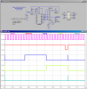
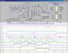
now i have got as far as working out i might be able to use a 74160 synchronous decade counter coupled to a 74161 synchronous 4-bit counter, giving me the total 24,
but i am not sure if i am thinking in the right terms, is it right that once the binary counter has reached 15 i can get that to start the decimal counter going and then when that gets to 9 they trigger the LED and then both reset?
its for a BPM meter,
thanks everyone
i have a signal similar to sync24 used in music tempo syncing, and i want to count it so that every time the signal has gone high and back low 24 times it flashes an LED and resets the count.
now i have got as far as working out i might be able to use a 74160 synchronous decade counter coupled to a 74161 synchronous 4-bit counter, giving me the total 24,
but i am not sure if i am thinking in the right terms, is it right that once the binary counter has reached 15 i can get that to start the decimal counter going and then when that gets to 9 they trigger the LED and then both reset?
its for a BPM meter,
thanks everyone
")