just checked and that is the same diagram i followed, the pins discribed are wired as they should be,
but when i said Q2 i was looking at the chip upside down, its Q5 that does nothing
hi,
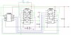
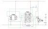
Are you saying Q5 does nothing even when the RESET pin of the 4024 is tied to 0V.??
If the RESET is 'fully' connected as shown in Mike's circuit, then Q5 will be a very pulse which you will NOT see on the test LED.
I would suggest that you, for testing, connect the RESET pin #2 to 0V.
All the Q's should flash your LED test probe.
EDIT:
Checked Mike's original LTS plot output and it shows that Q5 should be long enough to see a flash.
Last edited:
")
")