Continue to Site

Welcome to our site!

Electro Tech is an online community (with over 170,000 members) who enjoy talking about and building electronic circuits, projects and gadgets. To participate you need to register. Registration is free. Click here to register now.

  • Welcome to our site! Electro Tech is an online community (with over 170,000 members) who enjoy talking about and building electronic circuits, projects and gadgets. To participate you need to register. Registration is free. Click here to register now.

Converting 12V Dumb RGB Lights to Intelligent Nodes (WS2811) 20ma-400ma

Status
Not open for further replies.

EvilGenius

Member
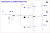
Objective: This circuit converts a 12V common anode biased RGB (or single color) module to a smart node with simple and low cost components.
Interface allows color control of individual RGB modules and control of many pixels via common WS2811 based controllers. (512 colors)
The 4-wire RGB+ system can still be utilized to accommodate the required +12,Data,Gnd wires. The 4th wire (extra) can be used as a power injection to boost the power.
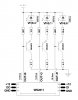
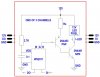
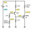
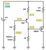
The heart of the circuit is the beloved WS2811 chip that allows SPI communications. Data comes in processed and passed on to the next chip. For details please refer to datasheet of WS2811. Once data is received by WS2811 and latched, outputs of the chip go into action reflecting the color code on its output in the form of current sinking PWM. These outputs are then fed into a pnp transistor to be inverted and then fed into an npn transistor to be amplified and inverted once again. The need for two transistors serves two purposes. 1) Lower the voltage across the load transistor (Vce of NPN) as close to zero as possible 2) Allow inversion of logic to accommodate the Common Anode RGB module. The system is designed to push Vce down close to 0.2v. The lower the Vce, the brighter the LED and the less power dissipation by load transistor. Rset is utilized to set the base current of NPN which in turn controls the LED current.
The formula below calculates the value of Rset vs desired LED current. Where possible it is recommended to utilize the calculated resistor value to set the current accurately. If such resistor value is not easily available, use the Rounded DOWN closest available value.
Rset=507.76/(LED Current)
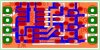
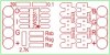
The SMD version with dimensions of 0.5 x 1.0 inches allows for inline use! Simply disconnect the 4-wires from old controller, connect the new SPI controller, and connect the interface to the newly labeled wires and you are good to go. Connect plus, ground, data out of first module to plus, ground, data in of the second module and keep going.
 

Attachments

  • SCHEMATICS.jpg
    SCHEMATICS.jpg
    127.9 KB · Views: 1,321
  • ALL.jpg
    ALL.jpg
    58.3 KB · Views: 480
  • SILK.jpg
    SILK.jpg
    52 KB · Views: 474
  • TOP.jpg
    TOP.jpg
    48.1 KB · Views: 425
  • BOTTOM.jpg
    BOTTOM.jpg
    27 KB · Views: 427
Last edited:
Hey there Ron
Liked the idea of simplifying my circuit but your modification wont work for common anode RGB. The LEDs needs to be fed from the top and controlled from the bottom. It is good for common cathode RGB though.

BTW I designed a SMD version of my last post for you. 0.5x1.2 inches if you want it. The project was a success!
 
Last edited:
RGB BOOSTER 12V COMMON ANODE (4A/CHAN)
Here is an opamp based RGB booster. LM324 is a quad opamp with wide supply range of 3V-30V.
First opamp generates the Vref for the rest of opamps, while supplying LM324 Vdd with 4V..
Outputs NMOS can be selected to sink 4A per each channel. SMD parts can fit on a 0.5 x 0.9 inch pcb. Inputs and outputs are isolated from each other providing for short circuit protection and power surges from the input.
 

Attachments

  • RGB Booster.jpg
    RGB Booster.jpg
    199.8 KB · Views: 515
Last edited:
RGB BOOSTER 12V COMMON ANODE (4A/CHAN) WITH TRANSISTORS
Here is the transistorized version.
 

Attachments

  • RGB Booster Transistors.jpg
    RGB Booster Transistors.jpg
    136.8 KB · Views: 683
RGB BOOSTER, OR WS2811 INTELLIGENT NODE
12V 4A/CHAN COMMON ANODE RGB DRIVER

This circuit could be utilized as an RGB booster to increase the output current capability to 4A per channel.
Or convert a Dumb RGB pixel to an intelligent pixel with 4A per channel output.
For RGB Booster simply remove WS2811 Outputs from the circuit and connect them to RGB inputs.
This circuit is one of 3 channels interfacing with a common anode RGB module.
Resistors are selected to be identical to reduce part variation.
Driver has a low current consumption (less than 3ma, 36mw), making it very efficient.
Utilizing a low ON-Resistor NMOS on the output allows for reduction of voltage drop to 45mv (very low power dissipation of 8.1mw at 4A which requires no heat-sinks nor a large thermal pad on pcb for SMD parts), allowing maximum brightness of LED's.
12V pixels need to be biased for 12v with its own appropriate series resistors. Pixels can be high power RGB, cluster of RGB modules, or a long run of RGB strip (10 meters-33 feet).
 

Attachments

  • WS2811 12V 4A-CHAN INTELLIGENT RGB DRIVER.jpg
    WS2811 12V 4A-CHAN INTELLIGENT RGB DRIVER.jpg
    97.4 KB · Views: 570
RGB BOOSTER, OR WS2811 INTELLIGENT NODE, 12V 5A/CHAN COMMON ANODE RGB DRIVER (Designed for NMOS that requires 10v Vgs)
Similar to the circuit above with LED Current boosted to 5A. Since most SMD (SOT-23) NMOS (which allow 5A drain current) require Vgs of 10v, the circuit was modified to accommodate this requirement. Same rule applies: Remove WS2811 and ground from the circuit and replace with input (R,G, or B) for current boosting. Otherwise the circuit with WS2811 will act as an intelligent node with 5A per channel output for high power common anode RGB modules. NMOS: R(on)=37-100 m-ohm, Pd=1W-19W, I-D=5A, Vgs=+-12v, Vth=0.8v-2.5v
 

Attachments

  • WS2811 INTELLIGENT NODE 5A.jpg
    WS2811 INTELLIGENT NODE 5A.jpg
    91.2 KB · Views: 486
Would this work (I used your diagram from post #2 Ron):

2016_09_04_Iss1_WS2811_LED_driver_ver_1.png
 
Hello Spec
The answer is NO. This is why...
Consider that your Pixel is pre-biased for 12v (i.e: it has series resistors that sets the LED currents already)
Also WS2811 output modulates between 0.63v and Vcc(12v) and it never reaches zero potential.
Per your diagram we have 0.63v for WS and then add Vbe (roughly 0.7v) to it. Now your lower potential (ground) of your pixel is raised to 1.33v and voltage across your pixel will be 12-1.33=10.67v instead of 12v. In this case your LED's will dim quite a bit. This also causes the Vce to rise to 1.33v; multiply that by the current thru the transistor (LED current) and you have a massive power dissipation that 2N4403 cannot handle! (Poof)
If you look up the datasheet for 2N4403 (TO-92 package), you will see that maximum current rating is 600ma while max Power Dissipation is 625mw.
The added NPN (or NMOS), the second transistor, allows Vce (load) to drop to around 0.2v (due to low ON resistance) while allowing large amount of current (4A) to go thru it (max Pq=0.8w).
If your pixel is not pre-biased, then you can compensate for this voltage difference by adjusting your pixel series resistor. But now you are redesigning your pixel and is no longer plug and play! I did another post for a ws2811 constant current interface that resembles your diagram. Look it up.

Yes, but apart from those points, do you like the circuit?:p

I must admit I didn't do an analysis of the circuit; it was just an idle thought while I was watching the US tennis open.

By the way, a very thorough and succinct analysis you did.:cool:

spec

UPDATE: another problem with the circuit is that the emitter/base junction is vulnerable.
 
Last edited:
Yes, but apart from those points though do you think the circuit will work?:p

spec

If you are asking me if I can make your circuit work, then here is the analysis and adjustments you need to make:
1- You need to add a resistor between collector and ground in the value of 2.8 ohms (1W)
2- With 100 ohm feedback resistors you have, your Vws increases to 0.75v (Vb)
3- Your Vbe is roughly 0.7v with Ve of approxim. 1.45v
4- With Rc=2.8 ohm, your Vc is now 1.25v, with Vce of 0.2v
5- Your Transistor gain is about 48.5, and Ie/Ib=49.5 about
6- Ib=9.1ma, Ir=(current thru 100 ohm)=7.3 ma, total current thru WS=16.4ma (good since max is 16.5ma)
7- Voltage across your pixel is 10.55v (need to adjust your series resistors)
8- Your max LED current per channel is 450ma
9- Your Pq= 0.2 x 0.450 = 90mw (good to go)
10- This should hold well for a constant current of 450ma or so per channel
11- You are going to have a nice small smd pcb with a bulky resistor on it (per channel)
12- You also need a very tight resistor tolerances (1% max) since 0.1v change could cause a LED current to fluctuate 20ma or so in either direction!
 
Last edited:
If you are asking me if I can make your circuit work, then here is the analysis and adjustments you need to make:
1- You need to add a resistor between collector and ground in the value of 2.8 ohms (1W)
2- With 100 ohm feedback resistors you have, your Vws increases to 0.75v (Vb)
3- Your Vbe is roughly 0.7v with Ve of approxim. 1.45v
4- With Rc=2.8 ohm, your Vc is now 1.25v, with Vce of 0.2v
5- Your Transistor gain is about 48.5, and Ie/Ib=49.5 about
6- Ib=9.1ma, Ir=(current thru 100 ohm)=7.3 ma, total current thru WS=16.4ma (good since max is 16.5ma)
7- Voltage across your pixel is 10.55v (need to adjust your series resistors)
8- Your max LED current per channel is 450ma
9- Your Pq= 0.2 x 0.450 = 90mw (good to go)
10- This should hold well for a constant current of 450ma or so per channel
11- You are going to have a nice small smd pcb with a bulky resistor on it (per channel)
12- You also need a very tight resistor tolerances (1% max) since 0.1v change could cause a LED current to fluctuate 20ma or so in either direction!

Thanks, but I was only joking.:)

The circuit of post #8 is a non starter.:banghead:

Where do EvilGeniouses live? or do they prefer to keep that private.

spec
 
Last edited:
Where do EvilGeniouses live? or do they prefer to keep that private.

spec
Home is Florida
I have converted all my Dumb RGB to intelligent nodes with 3-wire system. I love it. I can address 170 pixels (one universe with additional expansion) with a simple and inexpensive controller. I also have the capability of switching to DMX with a simple dongle and have an entire synchronized light show!
 
Last edited:
It would be handy to put where you are from next to 'Location' on your user page so that it shows in the window next to your posts. This is a rant with me because it helps to know where a person is from, it is also interesting and helps a bit to understand a person's point of view and the components they are liable to have access to and also their mains voltage and frequency.

The misus and I had a very enjoyable couple of weeks at Clearwater Beach near Tampa.:cool:

For an 'average Joe' you seem to have a good grasp of electronic design and a logical approach.:)

spec
 
it is also interesting and helps a bit to understand a person's point of view...
spec
I was the kid that took things apart to see what was inside them. I look at the world and think how I can simplify it for others by doing the clever thinking myself long and hard. Sometimes my best ideas and solutions come to me in my sleep, waking up writing them down to implement in the morning. I can also visualize computer codes and complex circuits in my mind and in one sitting draw it all out and build it in a day. It gives me a sense of accomplishment and leaves my friends and family at amaze sometimes. Hence the name...
 
Here is a constant current ws2811 that I mentioned that I did in April 2016.
 

Attachments

  • image.jpeg
    image.jpeg
    130.7 KB · Views: 465
You have a lot in common with many people on ETO: an inquiring and inventive mind, as discussed in the thread 'Is there an Engineering Type' in 'Members Lounge' :)

I expect you know that there is an 'Evil Genius' magazine and related books.

spec
 
Status
Not open for further replies.

Latest threads

New Articles From Microcontroller Tips

Back
Top