I am trying to get a DC input to pulse two different relays when it goes high or low.
DC input = low then goes high: relay one pulses for 1 second
DC input = high then goes low: relay two pulses for 1 second
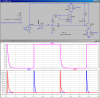
I found a 555 timer circuit that will pulse when it goes high (half of what I need), but I need it to pulse separate output when going low.
trigger circuit
Basically, I need it to duplicate this operation on the trailing edge of the clock signal as well but on a different output.
I have a handful of 555s and 556s at my disposal.
DC input = low then goes high: relay one pulses for 1 second
DC input = high then goes low: relay two pulses for 1 second
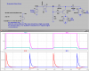
I found a 555 timer circuit that will pulse when it goes high (half of what I need), but I need it to pulse separate output when going low.
trigger circuit
Basically, I need it to duplicate this operation on the trailing edge of the clock signal as well but on a different output.
I have a handful of 555s and 556s at my disposal.
")