Continue to Site

Welcome to our site!

Electro Tech is an online community (with over 170,000 members) who enjoy talking about and building electronic circuits, projects and gadgets. To participate you need to register. Registration is free. Click here to register now.

  • Welcome to our site! Electro Tech is an online community (with over 170,000 members) who enjoy talking about and building electronic circuits, projects and gadgets. To participate you need to register. Registration is free. Click here to register now.

computer Christmas lights

MrDEB

Well-Known Member
years ago I assembled a Compurterized Christmas light display but since sold the entire setup.
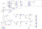
I recall the SSR or triac boards used an opti-isolator, couple resistors but instead of using a computer, I want to just use a PIC to drive the opti_isolator. Just started looking for leftover plans and parts but figure would ask first.
 
The7805 VR can handle 12V. My homemade circuit from 1988 uses a 14VDC wallpack, a 555 timer, a 4017 counter, and four 4N25 optos feeding TIC102 triacs. The flash rate is fixed by a resistor, but any resistance component can be subbed for different results. My circuit has worked outdoors down to -35C/ -31F with a gentle breeze keeping it cooled.
Still works after all these years, can also get replacement components.
 
Received my boards then assembled one. Wrote a testing code and going to test today. Code is Swordfish basic. Plan is to use a CASE/SELECT to randomize the cake sprinkles. see LedMatrix4x4 module
Code:
{
*****************************************************************************
*  Name    : UNTITLED.BAS                                                   *
*  Author  : [select VIEW...EDITOR OPTIONS]                                 *
*  Notice  : Copyright (c) 2022 [select VIEW...EDITOR OPTIONS]              *
*          : All Rights Reserved                                            *
*  Date    : 11/10/2022                                                     *
*  Version : 1.0                                                            *
*  Notes   :  RYDERWOOD SIGN START 11/10/22                                                              *
*          :                                                                *
*****************************************************************************
}
Device = 18F2221
Clock = 8

Include "intosc.bas"   
#option SWORDFISH_SE = true


Include "setdigitalio.bas"//Include "SetDigitalIO.bas"
Include "utils.bas"
Include "Convert.bas"
Include "ledmatrix_4X4"


//12 VOLT LED STRIPS
Dim R As PORTA.0
Dim Y As PORTA.1
Dim D As PORTA.2
Dim E As PORTA.3
Dim R_1 As PORTA.4
Dim W As PORTA.5
Dim o As PORTA.6
Dim D_1 As PORTA.7
Dim nc_1 As PORTB.0  //not used
Dim nc_2 As PORTB.1  //not  used

//CAKE SPRINKLES CATHODES USING MOSFETS
Dim Row_1 As PORTB.2
Dim Row_2 As PORTB.3
Dim Row_3 As PORTB.4
Dim Row_4 As PORTB.5

//HEADLIGHT ON TRAIN ENGINE
Dim Head_light As PORTC.7

//CANDLE FLAMES
Dim Flame1 As PORTC.0
Dim Flame2 As PORTC.1
Dim Flame3 As PORTC.2

// SPRINKLES ANODES
Dim RED As PORTC.3
Dim WHITE As PORTC.4
Dim BLUE As PORTC.5
Dim GREEN As PORTC.6


TRISA = 0   //ENABLE OUTPUTS
TRISB = 0
TRISC = 0

 while true
       NC_1 = 1   //TURN ON MOSFET ON B.0   TESTING 11/11/22
       DELAYMS(1000)
       TOGGLE (NC_1)
       DELAYMS(1000)
      
       RED = 1  //TURN ON LED ON C.3 "CAKE SPRINKLES"
       ROW_1 = 1
       DELAYMS(500)
       TOGGLE(ROW_1)
 WEND
 
I excluded the ledmatrix4x4 module and changed part of the code, but the led does not blink. the mosfet does not turn off?
Code:
 while true
       NC_1 = 1   //TURN ON MOSFET ON B.0   TESTING 11/11/22
       DELAYMS(1000)
       NC_1 = 0
       DELAYMS(1000)
      
      ' RED = 1  //TURN ON LED ON C.3 "CAKE SPRINKLES"
       ROW_1 = 1
       DELAYMS(1000)
       row_1 = 0    //turn off mosfet
       delayms(2000)
      
 WEND
 
a schematic should help. Trying to toggle the rows while C-3 - C.5 (colums) are left HIGH
The rows are B.2-B.5 these have the P mosfets. Yes I checked for grounded Drain pins no grounds but 1.64 M ohms to ground.
 

Attachments

  • sign brd 11_12_22.png
    sign brd 11_12_22.png
    72.6 KB · Views: 156
The second thing - you say "Trying to toggle the rows while C-3 - C.5 (colums) are left HIGH"
If that's the case then you need to make C.3-C.5 high.

Try:
Code:
{
*****************************************************************************
*  Name    : UNTITLED.BAS                                                   *
*  Author  : [select VIEW...EDITOR OPTIONS]                                 *
*  Notice  : Copyright (c) 2022 [select VIEW...EDITOR OPTIONS]              *
*          : All Rights Reserved                                            *
*  Date    : 11/10/2022                                                     *
*  Version : 1.0                                                            *
*  Notes   :  RYDERWOOD SIGN START 11/10/22                                 *
*          :                                                                *
*****************************************************************************
}
Device = 18F2221
Clock = 8

Include "intosc.bas"   

#option DIGITALIO_INIT = true
Include "setdigitalio.bas"
'Include "ledmatrix_4X4"

//12 VOLT LED STRIPS
Dim R    As PORTA.0     // channel_1
Dim Y    As PORTA.1     // channel_2
Dim D    As PORTA.2     // channel_3
Dim E    As PORTA.3     // channel_4
Dim R_1  As PORTA.4     // channel_5
Dim W    As PORTA.5     // channel_6
Dim O    As PORTA.6     // channel_8
Dim D_1  As PORTA.7     // channel_7

Dim NC_1 As PORTB.0     //not used, channel_9
Dim NC_2 As PORTB.1     //not  used, channel_10

//CAKE SPRINKLES CATHODES USING MOSFETS
Dim ROW_1 As PORTB.2
Dim ROW_2 As PORTB.3
Dim ROW_3 As PORTB.4
Dim ROW_4 As PORTB.5

//CANDLE FLAMES
Dim FLAME1 As PORTC.0   // flame_1
Dim FLAME2 As PORTC.1   // flame_2
Dim FLAME3 As PORTC.2   // flame_3

// SPRINKLES ANODES
Dim RED    As PORTC.3   // colum-1   
Dim WHITE  As PORTC.4   // colum-2
Dim BLUE   As PORTC.5   // colum-3
Dim GREEN  As PORTC.6   // colum-4

//HEADLIGHT ON TRAIN ENGINE
Dim HEAD_LIGHT As PORTC.7   // HEAD LIGHT

// before enabling the outputs, init all LAT registers low
LATA = 0
LATB = 0
LATC = 0

TRISA = 0   //ENABLE OUTPUTS
TRISB = 0
TRISC = 0

// "Trying to toggle the rows while C-3 - C.5 (colums) are left HIGH"
// make all column outputs high
RED = 1
WHITE = 1
BLUE = 1
GREEN = 1

while true
    NC_1 = 1   //TURN ON MOSFET ON B.0   TESTING 11/11/22
    delayms(1000)
    NC_1 = 0
    delayms(1000)
    
    ROW_1 = 1  //TURN ON LED ON C.3 "CAKE SPRINKLES"
    delayms(1000)
    ROW_1 = 0    //turn off mosfet
    delayms(2000)
wend
 
yes I measure 5+ at pin 20
While I was contemplating this issue of the Mosfets not turning off I remembered I failed to put B.2 - B.5 LOW.
I don't recall using LAT before., will give it a try.
Have yet to check the Mosfets on Channel 1 - 10
Thanks
 
back to the drawing board
the LEDs on row_1 - Row_3 turn on but do not turn off
Row_4 nothing


Code:
// before enabling the outputs, init all LAT registers low
lata = 0
latb = 0
latc = 0


TRISA = 0   //ENABLE OUTPUTS
TRISB = 0
TRISC = 0
red = 1
white = 1
blue = 1
green = 1
row_1 = 0
row_2 = 0
row_3 = 0
 while true
 r = 1
 y = 1
 d = 1
 e = 1
 r_1 = 1
 w = 1
 O = 1
 d_1 = 1
 nc_2 = 1
 
       NC_1 = 1   //TURN ON MOSFET ON B.0   TESTING 11/11/22
       DELAYMS(1000)
       NC_1 = 0
       DELAYMS(1000)
      
      ' RED = 1  //TURN ON LED ON C.3 "CAKE SPRINKLES"
      
       ROW_1 = 1      //enable the mosfet on row_1 which grounds the cathode through the mosfet
       DELAYMS(1000)
       Row_1 = 0    //turn off mosfet
       delayms(1000)
       row_2 =1
       delayms(1000)
       row_2 = 0
       delayms(1000)
       ROW_3 = 1      //enable the mosfet on row_1 which grounds the cathode through the mosfet
       DELAYMS(1000)
       Row_3 = 0    //turn off mosfet
       delayms(1000)
       row_4 =1
       delayms(1000)
       row_4 = 0
       delayms(1000)
 WEND
 
I don't recall using LAT before., will give it a try.

When you set a port outputs you can use either 'PORTx =' or 'LATx ='... swordfish will always write to the LAT register for you, so these generate the same code:
Code:
PORTA = $55
LATA = $55

PORTB.0 = 1
LATB.0 = 1
 
Well I figured out what was wrong with row_4 and now it works but none of the rows are toggling.
I swapped out the 1K GATE resistor for 150ohm resistor.
Going to check the IRF 520 mOSFETS
 
The SSM3K341R mosfets seem like they are shorted https://www.taydaelectronics.com/datasheets/files/A-5944.PDF
The DRAIN TO SOURCE still will not turn off measured the gate resistor as well as the Gate to ground 10k resistor.
All measure correctly. I measured the voltage at the gate/10k resistor junction (this comes from the pic) It measures 0 except about every 10 seconds it jumps to 4.95 volts brieftly then back to 0.
Contemplating removing the mosfet and wire in one of the IRF520s (bush fix just for testing) to see if it then will toggle the Row_1.
Maybe a wrong mosfet or?
 
I took some time away from the MOSFET issue (the SSM3K341R) and got other parts of this "ART" project completed but now back to the issue of the MOSFETS (ALL 4 OF THEM). I checked for shorts (none)
The MOSFETS are ON with or without any voltage on the GATE.
When I place an LED on any row that row voltage drops to .495 volts (no real surprise)
The voltage on any row without any LED is 0 volts
I checked the test points marked SPK_1 - 4 when the desired row is enabled and it has 4.95 volts
The test points are 0 when OFF
I changed the MOSFET but no difference
What am I missing here?
 

Attachments

  • Screenshot (14).png
    Screenshot (14).png
    178.4 KB · Views: 138
contemplating treating the 16 LEDs as a matrix. removing the MOSFETS then just use a matrix module.
Each row (4 rows) are sequently taken low and the columns sequentially go high. the code needs editing but this might work?
Code:
{
*****************************************************************************
*  Name    : UNTITLED.BAS                                                   *
*  Author  : [select VIEW...EDITOR OPTIONS]                                 *
*  Notice  : Copyright (c) 2020 [select VIEW...EDITOR OPTIONS]              *
*          : All Rights Reserved                                            *
*  Date    : 3/15/2020                                                      *
*  Version : 1.0                                                            *
*  Notes   :                                                                *
*          :                                                                *
*****************************************************************************
}
Module ledmatrix_4X4


//LED MATRIX
Dim RED As PORTC.3
Dim WHITE As PORTC.4
Dim BLUE As PORTC.5
Dim GREEN As PORTC.6
Dim ROW_1 As PORTB.2
Dim ROW_2 As PORTB.3
Dim ROW_3 As PORTB.4
Dim ROW_4 As PORTB.5
// make led pins outputs and turn them all off
Public Sub AllOff()
    // ALL ANODES
    High(RED)
    High(WHITE)
    High(BLUE)
    High(GREEN)
   // High MAKE ALL COLUMS HIGH
    // turn off rows ALL CATHodes
    Low(ROW_1)
    Low(ROW_2)
    Low(ROW_3)
    Low(ROW_4)
End Sub

// turn on a single led
//  led_no = 0 -> nothing on (all off)
//         = 1-12 -> turn on specified led
// the routine ignores the comments above and sets the leds "in order"
// so it may not match the (unknown) schematic
// it's long-hand so it can easily be adjusted to match

Public Sub SetLed(led_no As Byte=0)
    AllOff()
    Select (led_no)
        // COL1
        Case 1      // 1-4 COLIUMS
            RED = 1        //high
            ROW_1 = 1        //HIGH TURNS ON MOSFET
        Case 2      // row1, col2
            WHITE= 1
            ROW_1= 1        //HIGH TURNS ON MOSFET
        Case 3      // row1, col3
            BLUE = 1
            ROW_1 = 1        //HIGH TURNS ON MOSFET
        Case 4     // ROW 1 COL 4
            GREEN = 1
            ROW_1 = 1        //HIGH TURNS ON MOSFET
            
            
        //COL2   
         Case 5      // 1-4 COLIUMS
            RED = 1        //high
            ROW_2 = 1        //HIGH TURNS ON MOSFET
        Case 6      // row1, col2
            WHITE= 1
            ROW_2 = 1        //HIGH TURNS ON MOSFET
        Case 7      // row1, col3
            BLUE = 1
            ROW_2 = 1        //HIGH TURNS ON MOSFET
        Case 8     // ROW 1 COL 4
            GREEN = 1
            ROW_2 = 1        //HIGH TURNS ON MOSFET
            
            
       // COL3   
            
         Case 9      // 1-4 COLIUMS
            RED = 1        //high
            ROW_3 = 1        //HIGH TURNS ON MOSFET
        Case 10     // row1, col2
            WHITE= 1
            ROW_3 = 1        //HIGH TURNS ON MOSFET
        Case 11      // row1, col3
            BLUE = 1
            ROW_3 = 1        //HIGH TURNS ON MOSFET
        Case 12     // ROW 1 COL 4
            GREEN = 1
            ROW_3 = 1        //HIGH TURNS ON MOSFET


        //COL4   
         Case 13      // 1-4 COLIUMS
            RED = 1        //high
            ROW_4 = 1        //HIGH TURNS ON MOSFET
        Case 14      // row1, col2
            WHITE= 1
            ROW_4 = 1        //HIGH TURNS ON MOSFET
        Case 15      // row1, col3
            BLUE = 1
            ROW_4 = 1        //HIGH TURNS ON MOSFET
        Case 16     // ROW 1 COL 4
            GREEN = 1
            ROW_4 = 1        //HIGH TURNS ON MOSFET
            
    End Select
End Sub
 SetLed()
// init
AllOff()

End Module
 
Please do the matrix properly,
Use an array to hold the 16 LEDs state.
Place 4 column values on the column pins.
Take ONE (the relevant one) of the row pins low.
Delay a suitable amount.
Take the row pin high.
Repeat for other three rows.

This way each LED has a 25% duty cycle rather than a 6.25% duty cycle.

I may have got rows and columns mixed up as I can't follow your schematics.

Mike.
Edit, I assume Swordfish can easily do interrupts so this could be done automatically. Yes?
 
REVISED LEDMATRIX4X4_1
Will try this out tomorrow
Code:
{
*****************************************************************************
*  R W B G   COLIUMS
   1 2 3 4   ROW_1
   5 6 7 8   ROW_2
   9 10 11 12 ROW_3
   13 14 15 16 ROW_4                                                  *
*          :                                                                *
*****************************************************************************
}
{
*****************************************************************************
*  Name    : LEDATRIX4X4_1.BAS                                                   *
*  Author  : [select VIEW...EDITOR OPTIONS]                                 *
*  Notice  : Copyright (c) 2020 [select VIEW...EDITOR OPTIONS]              *
*          : All Rights Reserved                                            *
*  Date    : 11/19/22                                                     *
*  Version : 1.0                                                            *
*  Notes   : edited version for 4 x 4 matrix                                                               *
*          :                                                                *
*****************************************************************************
}
Module ledmatrix_4X4_1


//LED MATRIX
Dim RED As PORTC.3
Dim WHITE As PORTC.4
Dim BLUE As PORTC.5
Dim GREEN As PORTC.6
Dim ROW_4 As PORTB.2
Dim ROW_3 As PORTB.3
Dim ROW_2 As PORTB.4
Dim ROW_1 As PORTB.5
// make led pins outputs and turn them all off
Public Sub AllOff()
    // ALL ANODES
    High(RED)
    High(WHITE)
    High(BLUE)
    High(GREEN)
   // High MAKE ALL COLUMS HIGH
    // turn off rows ALL CATHODES
    Low(ROW_1)
    Low(ROW_2)
    Low(ROW_3)
    Low(ROW_4)
End Sub

// turn on a single led
//  led_no = 0 -> nothing on (all off)
//         = 1-12 -> turn on specified led
// the routine ignores the comments above and sets the leds "in order"
// so it may not match the (unknown) schematic
// it's long-hand so it can easily be adjusted to match

Public Sub SetLed(led_no As Byte=0)
    AllOff()
    Select (led_no)
        // COL1
        Case 1      // 1-4 COLIUMS
            RED = 1        //high
            ROW_1 = 0        //LOW ENABLES LED#1
        Case 2      // row1, col2
            WHITE = 1
            ROW_2 = 0        //LOW ENABLES LED#6
        Case 3      // row1, col3
            BLUE = 1
            ROW_3 = 0        //LOW ENABLES LED#11
        Case 4     // ROW 1 COL 4
            GREEN = 1
            ROW_4 = 0        //LOW ENABLES LED#16
            
            
        //COL2   
         Case 5      // 1-4 COLIUMS
            RED = 1        //high
            ROW_1 = 0        //LOW ENABLES LED# 5
        Case 6      // row1, col2
            WHITE= 1
            ROW_2 = 0        //LOW ENABLES LED# 10
        Case 7      // row1, col3
            BLUE = 1
            ROW_3 = 0        //LOW ENABLES LED# 15
        Case 8     // ROW 1 COL 4
            GREEN = 1
            ROW_4 = 0        //LOW ENABLES LED# 4
            
            
       // COL3   
            
         Case 9      // 1-4 COLIUMS
            RED = 1        //high
            ROW_3 = 0        //LOW ENABLES LED# 9
        Case 10     // row1, col2
            WHITE= 1
            ROW_4 = 0        //LOW ENABLES LED# 14
        Case 11      // row1, col3
            BLUE = 1
            ROW_1 = 0        //LOW ENABLES LED#3
        Case 12     // ROW 1 COL 4
            GREEN = 1
            ROW_2 = 0        //LOW ENABLES LED#8


        //COL4   
         Case 13      // 1-4 COLIUMS
            RED = 1        //high
            ROW_4 = 0        //LOW ENABLES LED# 13
        Case 14      // row1, col2
            WHITE= 1
            ROW_1 = 0        //LOW ENABLES LED# 10
        Case 15      // row1, col3
            BLUE = 1
            ROW_2 = 0        //LOW ENABLES LED#7
        Case 16     // ROW 1 COL 4
            GREEN = 1
            ROW_3 = 0        //LOW ENABLES LED# 4
            
    End Select
End Sub
 SetLed()
// init
AllOff()

End Module
 
Do you have a schematic that shows ALL the parts?
The last one posted doesn't show the LED matrix or the IRF520's.

Mike.
Edit, I assume Swordfish can easily do interrupts so this could be done automatically. Yes?
Yes it could be done Mike, but that ain't gonna happen here!
 

Latest threads

New Articles From Microcontroller Tips

Back
Top