Continue to Site

Welcome to our site!

Electro Tech is an online community (with over 170,000 members) who enjoy talking about and building electronic circuits, projects and gadgets. To participate you need to register. Registration is free. Click here to register now.

  • Welcome to our site! Electro Tech is an online community (with over 170,000 members) who enjoy talking about and building electronic circuits, projects and gadgets. To participate you need to register. Registration is free. Click here to register now.

Class A-B amplifier simulation help

Status
Not open for further replies.
@unclejed613
you maked it more complex for me :D
That circuit is beyond my comprehension to understand
 
@unclejed613
you maked it more complex for me :D
That circuit is beyond my comprehension to understand

It is a very simple STANDARD audio amplifier circuit. Many audio amplifiers are made like it and also many opamps are made the same but with low power transistors.
If you don't understand it then you should learn about the basics of transistors.

Break it down into simple sections:
1) Q1 and Q2 are a differential amplifier.
2) Q3 is used for its high voltage gain.
3) Q4 is designed to apply a voltage that biases the output stage to avoid crossover distortion.
4) Q9 is a high impedance load for Q4 which helps Q4 have high voltage gain.
5) The output is an ordinary darlington complimentary class-AB output stage.
6) R6 and R7 apply AC and DC negative feedback.
 
i didn't mean to make it seem more complex. i was just demonstrating why having the resistors between the output transistors and the load as low a value as possible, is important. you were wondering why your circuit had no gain. with 10 ohm resistors used as the emitter resistors, not only did you not have voltage gain (which an emitter follower AKA a common collector amp never does), but you had also reduced the current gain. by using 10 ohm resistors, you actually created a voltage divider which gave you a 50% voltage loss. what you posted was a circuit that had very little current gain, and a voltage loss. it's supposed to be a current booster with very little voltage loss, which is why it's a good idea to use 0.1 or 0.22 ohm resistors there. what i posted was just to show what the effects would be if this circuit were used as part of an actual amplifier, not to confuse you with more circuits. there is a similar circuit that has an actual voltage AND current gain... but pay attention to the polarity of the transistors. this is an inverting amp, and runs class A. it has a voltage gain of 2.
 

Attachments

  • hp-amp.jpg
    hp-amp.jpg
    26 KB · Views: 971
I tried to make your circuit again and it is not giving me any gain. can you post your .asc file

can you explain me why you used two 0.47 resistors there ?
can we make this circuit without using diodes ? i mean normal biasing using votage devider should work ?

Edited -still not giving any gain
 

Attachments

  • Complimentary amp.asc
    1.7 KB · Views: 360
Last edited:
hi neptune,
Please post your LTspice asc files when you post a simulation image, it makes it much easier for others to help.:rolleyes:

EDIT:
Check the orientation of Q2 in your circuit compared to Jed's
 
Last edited:
I tried to make your circuit again and it is not giving me any gain. can you post your .asc file

can you explain me why you used two 0.47 resistors there ?
can we make this circuit without using diodes ? i mean normal biasing using votage devider should work ?

Edited -still not giving any gain

hi,
WHY are you using low power transistors in the output stages.???

Run this asc with BD131/2
 

Attachments

  • Complimentary amp.asc
    1.7 KB · Views: 303
Last edited:
Why is a class-A heater posted? This thread is about a more efficient class-AB output circuit.
 
that's what i get for trying to draw something from memory....... it was a class AB headphone amp from 1965. it was a little bit different, but the original circuit only runs class AB with 1.5V rails. any more than that and both devices are in conduction.
 
I tried to make your circuit again and it is not giving me any gain. can you post your .asc file

can you explain me why you used two 0.47 resistors there ?
can we make this circuit without using diodes ? i mean normal biasing using votage devider should work ?

Edited -still not giving any gain

so what's up with using a 1hz source?. i've looked back through your previosly posted .asc files and you have your signal source set up weird in many cases(in one you have it run 10 cycles of a 1khz sine wave then shut off with a 1 second sim time). also your simulation time is somewhat strange. i use a 1khz sine wave, and a sim time of 10ms. using a long sim time like 1 sec or 5 sec will cause a lot of whacky things to happen. you probably did this with my circuit, so if you did, you were coupling a 1hz signal through a 10uf cap, which doesn't work.

also, what kind of gain are you looking for, and how are you measuring or calculating it?
 
Last edited:
ok so now this is running , but i want to learn some theory behind it.
The current in resistances R5 and R6 are out of phase of each other, but we are still getting current in R7 how ?

and please dont look at my previous posts they were wrong and i am improving them.
 

Attachments

  • hoho.png
    hoho.png
    197.1 KB · Views: 379
  • Complimentary amp.asc
    1.6 KB · Views: 291
Last edited:
hi neptune,
I am sorry but are just not listening to the advice being posted.

STOP using 1Hz as a test frequency, also USE complementary medium power transistors in the output stages.

Use a test frequency of say 1KHz and BD13x medium power transistors

EDIT:
As a test reduce the test signal amplitude to say1mV, then remeasure R5/6/7 currents and it will give you a clue to what the problem is.

Look at this Sim asc... with the changes that have been pointed out over the past few days.
 

Attachments

  • Complimentary amp2.asc
    1.6 KB · Views: 317
Last edited:
actually the currents aren't out of phase... it's just the way that LTSpice measured them that shows them that way... if you turn R6 around 180 degrees with the MOVE tool, it will show the currents in phase.

so, if you go back to the original concept of a class AB amp, we can simplify the circuit a bit...

R2 has been turned around 180 degrees and LTSpice now correctly displays the current... notice we eliminated a couple of resistors by tapping the signal in between the diodes. the cap is very important in the sim because the voltage source resistance is ZERO and that would change the bias on the transistors. we always want to isolate the signal source in the sim, because real signal sources rarely exhibit the same behavior. we could put a source resistance figure in the source, but it's best to isolate it with a cap...

if you turn off the signal source, you'll see the idle current is 1.5mA
 

Attachments

  • AB-buffer.jpg
    AB-buffer.jpg
    79.7 KB · Views: 683
  • AB-buffer.asc
    1.6 KB · Views: 291
Last edited:
Hi Unclejed, where have you been?
The latest circuits are class-A heaters with the transistors operating in common-emitter (so there is voltage gain).
Yours and almost all other audio amps operate the transistors in class-AB as emitter-followers.
 
actually i introduced the "heater". i have a IEEE book from 1965 that had one in there, but it was running class AB from 1.5V batteries. when run at 5V rails it turns class A. went back to a modified version of the OP's original circuit, a class AB buffer. the opposed collector output stage can be run in class AB, but requires additional transistors, and it is called a CFP (complementary feedback pair). the CFP output stage has no voltage gain.

actually there's nothing really wrong with a "heater" if you are running from an adequate power supply, and use adequate cooling for the amplifier. not recommended to run from batteries though...

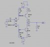
so to anser the OP's question about using diodes for bias:
the diodes provide the bias for the B-E junctions of the transistors, turning them on slightly. in a real world circuit the diodes would be thermally coupled to the output transistors to provide thermal compensation for the bias. when transistors heat up, their Vbe (voltage required to turn them on) changes at a rate of -2.2mV/degree C. this in turn increases the current through them, which increases the temperature, which increases the current.... until the transistor goes up in smoke. the diodes have the same temperature coefficient as the transistors, so the forward voltage across them decreases at the same rate as the Vbe of the transistors, and so reduce the bias, keeping the transistor current thermally stabilized.
 
Last edited:
> how does one know whats the power of transistor in LTspice ?
> how do we calculate the power of this circuit ? so that we can use low,medium,high powered transistor
in a real world circuit the diodes would be thermally coupled to the output transistors to provide thermal compensation for the bias.
> how does one do thermal coupling ?
 
thermal coupling is done by mounting the bias diodes or transistor on the same heat sink as the output transistors.

LTSpice can measure the currents through the transistors. choose transistors according to the current. if you use a 2N2222 in a circuit, and LTSpice says the current through the transistor is 5A, change it to an appropriate transistor, such as a 2N3055. that way when you actually build it you aren't going to let the Magic Blue Smoke out of a 2N2222.
 
> how does one know whats the power of transistor in LTspice ?

Run the simulation, let it finish.
Place the cursor pointer on the transistor, press and hold the ALT key [the cursor changes to a Thermometer] then left click the mouse.

You can use this method on any of the components on your circuit
 
Last edited:
how does one know whats the power of transistor in LTspice ?
You can use a Behavioral Voltage Source (the 'bv' component) and set its Value = collector current * CE voltage. The 'voltage' the bv produces is then a measure of the power.
how does one do thermal coupling ?
Clamp the diode to the transistors with an intervening layer of thermally conducting goo.
 
you can also plot the power directly. right click in a waveform plot pane, and then select Add Trace. in the formula line type (V(n001)-(V(p001))*Ic(Q1) then click OK (make sure you verify that the +5V rail is node N001 and that pointing a meter probe at the emitter of Q1 shows that point as P001). once it is plotted, you can also put the mouse cursor over the formula in the plot pane, hold down the control key, and left click the formula. it will show you the average power. doing the same thing with a voltage or current in the plot pane will show you the average and RMS values. with a 1khz source, putting in .four 1k V(n005) will put the distortion percentage into the spice error log (which can be opened in the View drop down list)
 
Last edited:
Place the cursor pointer on the transistor, press and hold the ALT key [the cursor changes to a Thermometer]
That doesn't work for me with transistors, but it does with passive components. What magic are you using, Eric?
 
Status
Not open for further replies.

Latest threads

New Articles From Microcontroller Tips

Back
Top