Continue to Site

Welcome to our site!

Electro Tech is an online community (with over 170,000 members) who enjoy talking about and building electronic circuits, projects and gadgets. To participate you need to register. Registration is free. Click here to register now.

  • Welcome to our site! Electro Tech is an online community (with over 170,000 members) who enjoy talking about and building electronic circuits, projects and gadgets. To participate you need to register. Registration is free. Click here to register now.

Circuit design assistance needed

Status
Not open for further replies.

WHYnot86

New Member
Hi

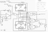
I am trying to put together a circuit that has 3 buttons for control.

Button 1: Power on/Select output
Button 2: Enable output
Button 3: Power off

Each output needs to oscillate the same bank of LEDs but at 5 different preset frequencies (frequency preset chosen with select button).

It is a battery powered circuit with a DC plug to be charged by a 7.2V 750mA DC adapter
Low battery and charging indicator LED
Overcharging protection
Batteries are 3.6V 600mAH NiMH

I have each circuit schematic for each function however I would like to know if there is an easier way to incorporate this into a 1 x IC cuircit at a reasonable cost.

Thanks in advance
 
Sure, how about a $3 Arduino mini?
 
Thanks for the help guys but I don't have much free time. Could you recommend someone who would be able to do this for me. I would of course be willing to pay them for their work.
 
Other than a PIC, Arduino, Rpi, or some other programmable part/device, no off the shelf IC can do everything you want.

Where are you located and what is this for?

ak
 
If you don't wan to use program, it can be done using few ICs found in the market. If you have good soldering skill let me know I can post a diagram, You told about 5 preset frequencies? can you list them? is it multiple of one base frequency or adjustable? 1:1 mark space ratio? (on & off) etc.
What are the circuits you have now to combine?
 
Please may you post a diagram.
Frequencies are all in multiples of 73Hz.
73, 146, 292, 584, 1168 and 2336Hz.
Ratio is 1:1.
 
That is six frequencies, not five. Do the frequency sources already exist, or is it part of the "project"?
When powered on, does the circuit remember the previous frequency setting or always start with frequency #1?
Is the output enable function momentary or latching?
How acdurate do the frequencies need to be?
What is the output impedance/output current/output waveform?
Is there a size limit for the circuit board?
How do you expect to get any help if you keep so many secrets?

5 chips so far, maybe 4.

ak
 
Last edited:
That is six frequencies, not five.
Apologies. Honest mistake.
Do the frequency sources already exist, or is it part of the "project"?
"Each output must oscillate..."
When powered on, does the circuit remember the previous frequency setting or always start with frequency #1?
If that was required I would have asked.
Is the output enable function momentary or latching?
Latch
How acdurate do the frequencies need to be?
Accuracy within 1Hz
What is the output impedance/output current/output waveform?
Impedance not available at the moment/400mA/square is fine
Is there a size limit for the circuit board?
80mm X 40mm can be double sided
How do you expect to get any help if you keep so many secrets?
Do you always ask so many questions 

Thanks for the assistance;)
 
I made a quick schematic, assumed 5 frequencies :), mark space was not made to 1:1 for all outputs since it will make more complicated. See the waveform expected. I did not show more details for connections, only basics. It can be with 6 ICs each may be 2$. 741, 4017 and some gates. You can modify it for 6 or up to 9 frequencies.

You can shift the AND gate for start / stop to last
 

Attachments

  • LED drive.jpg
    LED drive.jpg
    295.8 KB · Views: 280
Accuracy within 1Hz
You might have difficulty making your 2336Hz signal that accurate by simple analogue methods. Crystal-control may be called for.
 
Hi Alec
Thanks for your input. How would I do that? :nailbiting:

By the way, 73 Hz or above will not be visible to eyes. what you will see in all cases is like continuously glowing LEDs. If you explain your application or requirement a correct crystal and oscillator circuit can proposed.
 
I am aware that it will not be visible. I am experimenting with the effects of pulsed light at certain frequencies on vegetation.
 
Do you always ask so many questions
Only when the original question is poorly worded and lacks many details.
If that was required I would have asked.
Really? You didn't mention the required 400 mA (!!!) output current, the latching output enable, the frequency accuracy, the output waveform shape, or the size restriction...

I assumed the five-vs-six was a simple mistake, but your response does nothing to clear it up. Is it five or six?
"Each output" implies five (or six) outputs. But "the same bank of LEDs" implies one output. How many oscillating outputs do you require?
Is this a stepped PWM (constant pulse width/variable frequency) brightness circuit?
"Ratio is 1:1." Coming after a list of frequencies, I don't know what ratio you are talking about. Do you mean the output pulse width ratio, as in 50% duty cycle?
The circuit in post #12 divides the input clock by 1, 2, 3, 4, 5, not 1, 2, 4, 8, 16.
73 is a prime number, so the odds of finding an off-the-shelf high frequency crystal for the timebase is very low. Do you have a frequency counter to set up an oscillator?

ak
 
:facepalm::banghead::happy:
It is six.
Yes I mean 50% duty cycle.
There is only a single output to one bank of LEDs. No it is not a brightness circuit. See my previous post.

I look forward to your reply.
Please let me know what I forgot as I'm sure you will find something. ;)

Oh and no I don't have a frequency counter.
 
I wrote that response then it didn't send for a while. Now that I have more information -
Of course, more questions.
Is there any particular reason why your frequencies are at binary multiples? What about a logarithmic or Fibonacci sequence?
Is the 73 Hz base frequency related to the Schumann resonance frequency?
Square waves have significant harmonic content. Any thoughts about a more "pure" sinewave output?
For example, a circuit based on the 8038 function generator chip makes a sinewave with about 2%-5% distortion. Not audiophile quality, buy way less harmonic energy than a square wave. If the on/select button steps an analog multiplexer connecting one of 6 trimpots to the 8038, then you have 6 sinewave oscillator frequencies, all with identical, *stable* peak amplitudes, adjustable to whatever frequencies you want.

ak
 
Status
Not open for further replies.

Latest threads

New Articles From Microcontroller Tips

Back
Top