theyreinthehouse
New Member
Hi, hopefully this is the right place to post this question. I’m looking to build an oscillator. I have all the parts ready to order and I wanted to double check that I’m not making an obvious mistake. I’m completely new to this and I thought it would be worth a second opinion to know if the parts I found are correct based on the guide I’m following, if anyone has the time to take a look. Any pointers are appreciated.
Here’s a list of the parts based on the guide that I’m following:
1x 1k resistor,
1x 100k resistor,
1x 10k 16mm potentiometer,
1x 2N3904 transistor,
1x LED,
1X 10μF capacitor
And here’s the list of these parts that I’ve found and plan to order:
 irishelectronics.ie
irishelectronics.ie
irishelectronics.ie
irishelectronics.ie
irishelectronics.ie
irishelectronics.ie
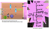
I’m planning to solder it on this strip board - https://irishelectronics.ie/epages/...ath=/Shops/950018241/Products/2439&Locale=en_ IE
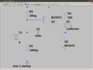
Here’s an illustration of the schematic from the video that I’m following -
Here’s a list of the parts based on the guide that I’m following:
1x 1k resistor,
1x 100k resistor,
1x 10k 16mm potentiometer,
1x 2N3904 transistor,
1x LED,
1X 10μF capacitor
And here’s the list of these parts that I’ve found and plan to order:
1K TruOhm 0.25 Watt Resistor - Irish Electronics.ie
1/2W Metal Film Resistor 15k Ohm -100k Ohm - Irish Electronics.ie
10K 16mm Linear Potentiometer - Irish Electronics.ie
2N3904 Audio Transistor NPN - Irish Electronics.ie
WHITE LED 5mm WATER-CLEAR - Irish Electronics.ie
TANTAL CAPACITOR 10µF / 16V - Irish Electronics.ie
I’m planning to solder it on this strip board - https://irishelectronics.ie/epages/...ath=/Shops/950018241/Products/2439&Locale=en_ IE
Here’s an illustration of the schematic from the video that I’m following -