Continue to Site

Welcome to our site!

Electro Tech is an online community (with over 170,000 members) who enjoy talking about and building electronic circuits, projects and gadgets. To participate you need to register. Registration is free. Click here to register now.

  • Welcome to our site! Electro Tech is an online community (with over 170,000 members) who enjoy talking about and building electronic circuits, projects and gadgets. To participate you need to register. Registration is free. Click here to register now.

Bjt transistors

Status
Not open for further replies.

Bdsdbehdad

New Member
Hey guys.
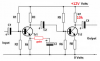
I want to know how can i design amplifier with cascade transistors .
Gain that i need is 100k.
Output swing minimum is 8v
Rout= 10k.
Rin= minimum is 50 ohm.
Thanks for answers.
 
Welcome to ETO

Show us your work.
 
For what frequency or frequency range?

Audio designs are very different from HF/VHF radio and different again from microwave frequencies etc..
 
since it's 10k output impedance it sounds more like video amp... or maybe a microphone preamp... one question first... is this homework assignment? or is there a practical use in mind?
 
Is the required gain 100k of voltage gain? Then the 8V of output swing needs an input swing of only 80uV.
 
For 10khz
Sorry it needs. 365 gain.

OK, in that case the "Hart JLH K1450" circuit from this page (around half way down) may suit your needs:

Leave out all the small value capacitors (less than 100nF) in the right hand half for flatter frequency response.
The gain can be made adjustable by replacing the 150 Ohm fixed resistor with a preset resistor (trimpot); 100 Ohm should be suitable.

That is an very low noise and low distortion design - you may not need that quality, but you do not say what the application is...
 
It is simple to cascade two transistors to make a gain of 365 and have an output swing of of 8V and an output of 10k ohms. Here is a simple design found in Google. If the first transistor has a gain of 40 and the second transistor has a gain of 9.125 then the distortion will be reduced.
 

Attachments

  • high gain amplifier.png
    high gain amplifier.png
    37.2 KB · Views: 221
It is simple to cascade two transistors to make a gain of 365 and have an output swing of of 8V and an output of 10k ohms. Here is a simple design found in Google. If the first transistor has a gain of 40 and the second transistor has a gain of 9.125 then the distortion will be reduced.

Except the output impedance won't be 10K, it will be less than that.
 
The output impedance of a common-emitter transistor is not less than its collector resistor value. It would be less if the collector has some negative feedback added.
My simulation shows that if the transistor with a 10k collector resistor is loaded with a 10k load then the output swing drops to exactly half, even when the emitter resistor is bypassed or not.
Therefore the output impedance is the collector resistance.
 

Attachments

  • transistor output impedance.png
    transistor output impedance.png
    70.8 KB · Views: 223
AG, that circuit has some serious distortion! - can't you see how asymmetric the output is?

This is the first waveform with a rotated version superimposed to show the difference:
transistor_distortion.png
 
AG, that circuit has some serious distortion! - can't you see how asymmetric the output is?
Of course the high gain transistor (2.4V output/10mV input= gain of 240) has distortion, the output is high level and there is no negative feedback.
As shown with an emitter resistor producing negative feedback and reducing the gain to 19.5, the distortion is much less.
 
Status
Not open for further replies.

Latest threads

New Articles From Microcontroller Tips

Back
Top