Continue to Site

Welcome to our site!

Electro Tech is an online community (with over 170,000 members) who enjoy talking about and building electronic circuits, projects and gadgets. To participate you need to register. Registration is free. Click here to register now.

  • Welcome to our site! Electro Tech is an online community (with over 170,000 members) who enjoy talking about and building electronic circuits, projects and gadgets. To participate you need to register. Registration is free. Click here to register now.

Bjt amplififer

Status
Not open for further replies.
As he's not posted the schematic in a sensible format I've no idea what it might be like?, but 4W RMS in to 4 ohms from 12V is easily (and commonly) doable, as done in all single ended car radio amplifiers.
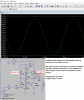
Install https://www.windows10download.com/ltspice-iv/
then .asc files open in this.
click stickman icon to run scope.
click any node(s) for voltage or components for current.
repeat after editing schematic values or adding, parts.
use move or drag hand icon (rubbers band mode keeps nodes connected)
voila!

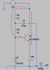
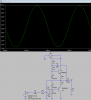
Car 12V 4W audio amps use many transistors in final stage in discrete or IC (>10k current gain, symmetry of bipolar gain, hence low distortion and maximum swing.) such that output impedance is <<1% of load R.
 
Last edited:
So at what point can we try for an answer(s)?
Most respondents to this thread seem to be all about showing off how smart and experienced they are instead of showing the TS what principle he/she needs to learn to solve the problem...
 
Here is a tutorial on Class A, Class B, and Class AB amplifiers that I found useful. Hope it helps the OP with the design aspect and modification of the circuit to his/her needs.
**broken link removed**

With my limited knowledge I recommend working backwards. Separate two phases of input/output (when input goes positive work the top transistor and when input is negative work the bottom transistor). Find out what output current and voltage is needed, set Vbe of complimentary transistors to 0.7v to obtain base, collector, emitter voltages and currents.
It also helps to utilize some transistor basics and shortcuts such as Ic/Ib=hfe (set to 100 to begin) and Ie=0.99 x Ic. Also set current below base to be 10 times Ib, and current above base to 11 times Ib. One can quickly calculate everything like a ladder. Then the currents and voltages for the third transistor which provides bias for the complimentary transistors can be calculated. At the final stage set the decoupling capacitors to create the bandwidth (or specific frequency operating window to isolate the biased transistor) and to create the smooth sine shape. From there on is making adjustment to obtain the optimum output gain, voltage, current and power rating. Just a few thoughts...
 
Last edited:
The original posting person said, "our project" and had specifications for it so it is probably a school assignment. I do not know why the teacher did not teach the basics first.
The required gain is very low so 3 transistors should be able to do it.
The small 2N4401 and 2N4403 transistors will get extremely hot but should be able to produce 1.24W into an 8 ohm speaker with the 12V supply.

I show simulations of the original circuit with its 30 ohms load and with an 8 ohm load.
I added bootstrapping and reduced the resistor values and show the simulation.
 

Attachments

  • amplifier with 30 then 8 ohms loads.png
    amplifier with 30 then 8 ohms loads.png
    48 KB · Views: 293
  • improved amplifier.png
    improved amplifier.png
    43 KB · Views: 292
I changed the load to 8 ohms so we can get 3 watts from a 12V supply.
problem: We need more current. The little output transistors can not with stand the heat and the current is very close to the max the part can with withstand. I chose 5A transistors not 600mA parts. These parts can connect to a heat sink to get rid of the heat.
upload_2016-9-5_14-28-46.png

Below is a graph of the old transistors. You can see the current gain is about 200 with current below 100mA. At 500mA the gain drops to 20. By choosing a bigger transistor there will be good gain at the desired current. So start at the load. Find what voltage, current and power you need. Choose transistors designed to work at that level.
upload_2016-9-5_14-36-7.png

To get 10x more current in the output you need (about) 10x the current in the bases. I changed the resistors to get about 10x more current through out the amplifier.

The goal is not clear to me. I think your teacher wants 10x more power out. So change the output transistors to parts that can work well at 10x the current.
-------------------------------------------------------
Another option: (every thing in this picture functions as one, very high gain transistor)
Increase the current and power capability of the output transistors AND (increase the current gain) so Q1 does not need to be changed. Q5= the old low current transistor. Q4= the new high current transistor.
Question: Why do I need two diodes? D3, D4
Question: What is Q5+Q6 called?
upload_2016-9-5_14-52-27.png
 
What is the purpose of C3 in your circuit?
With out C3:
When you turn on Q2 hard; there is little voltage across Q2 C-E. This will cause there to be very little voltage across R3. Q2 will not turn on well because you can not get base current. (no voltage - no current)
upload_2016-9-5_16-18-27.png

At steady state; (No signal) The output is at 6V or 1/2 supply. There is 3V of charge on C3.
Transistor on hard with on C3. Q2E=11V Q2B=11.7V So the current into the base is only 0.3V and (70+70) ohms. About 2mA (base current) is not enough current to get much emitter current.
Transistor on hard with C3! Because there is 3V stored on C3, when Q2E=11V the bottom end of C3=11V and the top end of C3=14V. Q2B=11.7V. Across R3 there will be 2.3V. 2.3V/70 ohms = 33mA. By adding C3 we increase the base current from 2 to 33mA. So the emitter current can be 16 times more.
upload_2016-9-5_16-22-56.png

This is called boot strapping.
Reach down, grab your shoe strings and pull hard. If you had gain like the transistor you could pull your self off the floor.
 

Attachments

  • upload_2016-9-5_16-17-59.png
    upload_2016-9-5_16-17-59.png
    12.9 KB · Views: 252

Thank you. I read a little about bootstrap and understand what you are describing. I also understand you want the discharge rate to be longer than transient input switching period. How did you come up with value? Based on longer than 1khz time period using 1/2pixfxc formula? How did you decide that the top of C3 is applied to the bottom 70 ohm and not, let's say, to the base directly? You need a resistor to slowly discharge it?
 
1/2pixfxc formula
Yes,
An audio amp should work to 20hz. (more or less) But right, if you are only amplifying 1khz then the cap should not discharge much in 1/1000.

What we are trying to do is make a little supply that is greater than 12V to pull up the base. We could have removed the resistor from +12V and connected it to a 15V supply and had similar results.
 
Yes,
An audio amp should work to 20hz. (more or less) But right, if you are only amplifying 1khz then the cap should not discharge much in 1/1000.
.
What are the cons to your bootstrapping in brief and should we be worries about cap discharging and transistor to shut off before the down cycle and even worse the next up cycle?

Thank you in advance for your answers. It helps me understanding designing them better.
 
Since audio frequencies go down to 20Hz then you want an audio coupling capacitor to have its reactance equal to or less than its load resistance. But this amplifier has three coupling capacitors so the reactance should be calculated at 20Hz/3= 6.7Hz.
The calculation is simply C= 1 divided by (2 x pi x R x f).

With a 12V supply the maximum output swing might be 8.5V p-p which is 3.0V RMS. Then for an output of 3W the load must be 3 ohms which is almost a dead short and the peak current will be 1.42A.
 
Ron, your amplifier has clipping at the bottom of the waveform. With your 4 ohm load its output power is only (10.4V - 2.0V)/2 divided by 2.828, squared, divided by 4 ohms= 2.2W. With a load that is 3 ohms then the output is 3W.
 
Ron, I zoomed your schematic so its details are visible:
 

Attachments

  • Ron's amplifier.png
    Ron's amplifier.png
    19.9 KB · Views: 273
I do not see any comments from OP. The least he could have said was thank you.
Thank you for your expert comments. It helped me learn more even though I find this type of amplifier not very practical.
 
I am a dirty old man and am surprised that I never noticed humping from darlington transistors.
 
Status
Not open for further replies.

Latest threads

New Articles From Microcontroller Tips

Back
Top