Continue to Site

Welcome to our site!

Electro Tech is an online community (with over 170,000 members) who enjoy talking about and building electronic circuits, projects and gadgets. To participate you need to register. Registration is free. Click here to register now.

  • Welcome to our site! Electro Tech is an online community (with over 170,000 members) who enjoy talking about and building electronic circuits, projects and gadgets. To participate you need to register. Registration is free. Click here to register now.

Basic thermostat

Status
Not open for further replies.

Straffan

New Member
Hi All

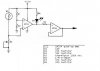
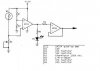
Attached is a simple thermostat circuit I found which would suit my need perfectly except that when the temperature reaches the pre-set level (set by trimpot R4) the LED lights as expected but the output pin on IC1B (LM324 op amp) goes low instead of high. How can I reverse this so that the LED lights when the output goes high intead of low ?

Thanks in advance for any help
 

Attachments

  • circuit_117.jpg
    circuit_117.jpg
    22 KB · Views: 1,368
Change position of led as shown and also interchange + an - inputs of first opamp. So opamp will now switch high at desired temperature. R5 serves no purpose as last opamp is ony a buffer and will have high input resistance already that won't load the previous stage.
 
TheOne said:
Change position of led as shown and also interchange + an - inputs of first opamp. So opamp will now switch high at desired temperature. R5 serves no purpose as last opamp is ony a buffer and will have high input resistance already that won't load the previous stage.

R5 might not be a bad idea. While it does not do anything in terms of functionality, I notice that the input of the buffer can be as high as 12V. If this buffer op amp runs off of 12V VCC as well, then its maximum input voltage will be 12 - 1.5 = 10.5V. And this is easily exceeded by the previous opamp. What is sometimes done so as not to damage the part is to put a current limiting resistor on the input, R5. It does not need to be 37K though.. as low as 1k would probably be fine.
 
This is an old 324 and will never switch rail to rail, maybe 11.5v if you are lucky. There's another problem though, the 324 is used as a comparator with no hysteresis which will cause the output to oscillate (might not be visible with the LED) when inputs are near the switching point. This will be worse when there is a bit of noise as well when using long wires with the ntc resistor.

EDIT: My databook shows that with a 30v supply the output is only capable to go to 26v typically. No spec is given for 12v supply but from my experience it will be near 11-11.5v Also databook states that either input can go to +32v without damage regardless of the value of supply V+
 
Thanks very much for all your input, I will have a go at this tonight and post how I got on tomorrow

Thanks again


:D
 
Will do, I will try to get it posted over the weekend once Ive drawn the whole thing up

Thanks again
 
here is as far as I have got to date. The idea was for one sensor to check if the wetback was above a set temp and the other to check if the water cylinder was below another set temp. when both went high the AND gate would go high turning on a pump circulating water to the cylinder.

so far so good

Thanks again for any help given

:D
 

Attachments

  • circuit_185.jpg
    circuit_185.jpg
    17.5 KB · Views: 753
Dear All

Did a bit of reading on the matter of switching a pump on and off this way (from the above diagram) via a triac. Is there anything to beware of due to the "inductive" load generated by the pump ?

Cheers and thanks
 
Here was how I was going to switch the pump on and off. Does anyone have any thoughts on preventing the posibility of inductive spikes that might occur ? The pump is rated at 100w

Many thanks again
 

Attachments

  • circuit_2.jpg
    circuit_2.jpg
    22 KB · Views: 526
Status
Not open for further replies.

Latest threads

New Articles From Microcontroller Tips

Back
Top