Hello,
I don't have much knowledge in electronics but I need to figure something out.
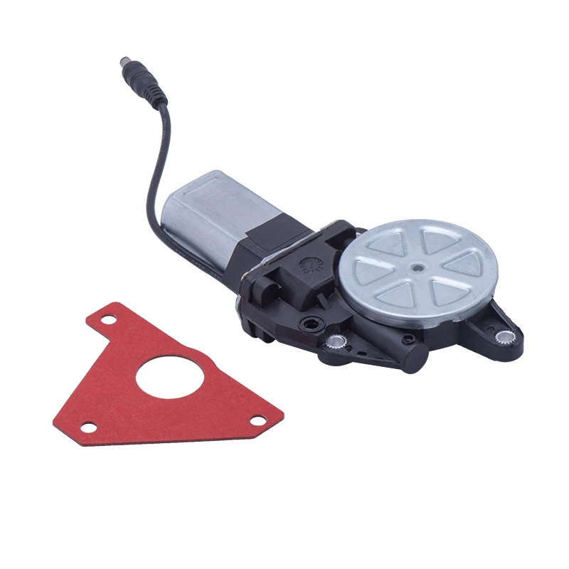
I have a valve that is controlled by a small motor that is connected to 12v with a switch. The switch is the one shown on the pictures below. When pushed one way it opens the valve (until it is released), when pushed the other way it closes the valve and when left in the middle it doesn't do anything.


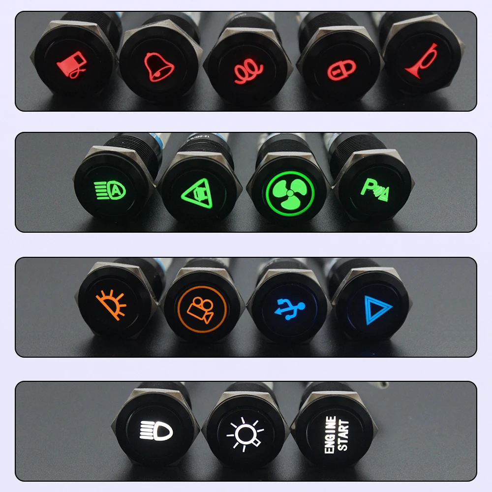
The problem is that I don't want to use that switch. It is first big and ugly but also unpractical. I want a switch with one position ON and on position OFF, like the ones below.

I need something to come in between that would act in such a way :
- when I flip the switch from 0 to 1 -> it activates the motor for 2 seconds to make sure the valve is open then it stops sending current to the motor
- when I flip the switch from 0 to 1 -> it activates the motor for 2 seconds the other way around to make sure the valve is closed then it stops sending current to the motor
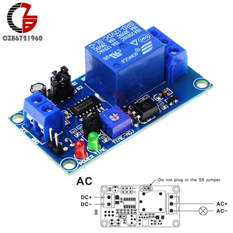
I found this item on Aliexpress that seem like it might help but I'm not sure if it wil work or how to set everything up :
 www.aliexpress.com
I'm quite sure on the other hand that my problem is quite basic and can be solved with a few items from Aliexpress for a small budget, I just don't know what to buy.
Any help would be appreciated ! thanks in advance.
Mathieu
I don't have much knowledge in electronics but I need to figure something out.
I have a valve that is controlled by a small motor that is connected to 12v with a switch. The switch is the one shown on the pictures below. When pushed one way it opens the valve (until it is released), when pushed the other way it closes the valve and when left in the middle it doesn't do anything.
The problem is that I don't want to use that switch. It is first big and ugly but also unpractical. I want a switch with one position ON and on position OFF, like the ones below.
I need something to come in between that would act in such a way :
- when I flip the switch from 0 to 1 -> it activates the motor for 2 seconds to make sure the valve is open then it stops sending current to the motor
- when I flip the switch from 0 to 1 -> it activates the motor for 2 seconds the other way around to make sure the valve is closed then it stops sending current to the motor
I found this item on Aliexpress that seem like it might help but I'm not sure if it wil work or how to set everything up :
1.18US $ 25% OFF|Dc 12v Time Relay Module Normal Open Time Delay Relay Timing Timer Relay Control Switch Adjustable Potentiometer Led Indicator - Relays - AliExpress
Smarter Shopping, Better Living! Aliexpress.com
I'm quite sure on the other hand that my problem is quite basic and can be solved with a few items from Aliexpress for a small budget, I just don't know what to buy.
Any help would be appreciated ! thanks in advance.
Mathieu
")
