Continue to Site

Welcome to our site!

Electro Tech is an online community (with over 170,000 members) who enjoy talking about and building electronic circuits, projects and gadgets. To participate you need to register. Registration is free. Click here to register now.

  • Welcome to our site! Electro Tech is an online community (with over 170,000 members) who enjoy talking about and building electronic circuits, projects and gadgets. To participate you need to register. Registration is free. Click here to register now.

Automotive 6 Volt Generator Transistor Voltage Regulator

Status
Not open for further replies.
Voltage_OV_Alarm_Sch.JPG


Voltage Over Volt Alarm Circuit CloseUp.jpg
 
That should work, though I'd move the sounder to pin 7 rather than pin 1; the IC dissipates less power that way.

I cannot see any reason for the previous problem, it sounds like it may have been a faulty pot?
 
Thanks for the reply!
It could be the voltage pot, It's kind of cheap and I had placed o rings that same day between it and the knob to make it stay in position however I did turn it a bunch and test it and push in and pull out etc and it would not act up. It seemed to be pushing on the current pot that was affecting it intermittent but that could be another bad connection not the source of the problem rather a intrerupt to the problem.
So on the LM311 alarm circuit it measured something like 16ma, not sure I understand why it would use more power with the load on pin 1 of the LM311, guess it has in internal resistor to ground on pin 1? But yes, I moved the voltage display and alarm circuit to the switched ignition voltage on the back of the ignition switch and hot glued the Piezo Sound Transducer to the back of the speaker grill behind the dash of the car.
LM311-Schematic.png
Emitter-Output-Circuit.png
 
Last edited:
not sure I understand why it would use more power with the load on pin 1 of the LM311, guess it has in internal resistor to ground on pin 1

With the output on the emitter, the output stage is being used in "emitter follower" mode and the minimum drop from V+ to the output is over 1.2V as the last transistor is driven by another emitter follower plus further stages.

With the emitter grounded, the output transistor is the only device (other than the current sense resistor) in the output current path and the voltage drop is much smaller, so much lower internal power dissipation in the device, for any given load current; plus more available voltage across the load.

See the full internal schematic on page 10:
 
Thanks for the explanation. The LM311's I have test at about .47 volts on the Emitters as I recall. It's good to know though.
The alarm circuit is not really loud enough and it kind of chirps now and then was worse till I added the capacitors. The only real problem with the alarm is it's hard to hear and at the same frequency of the air leaking around my vent window. It needs more hysteresis as its transition from off to on takes about 200 mv. In the test circuit I thought I saw it loading my 8 volt battery supply more when it was off and this was like hysteresis however on the car it lost that.

I was researching Automotive Alternator Electronic Voltage regulator IC's and they have built in fault sensing etc to make sure they stop the alternator from charging if the conditions are wrong.
As for our Electronic Generator VR design there may be possible ways to design it to not be able to fail High? Or perhaps use a FET that burns out easier than the 6 volt generator.
I have acquired several spare used 6 volt generators and regulators and now am toying with an Idea to build the ELECTRONIC VOLTAGE REGULATORs all open atop the Generators to show-off the electronics rather than potting it inside a old regulator housing. The only HeatSink needed really is the Output Diode but I do like having the MOSFET mounted too. My STPS40L15 O Ring diode is working perfectly with just .32 or so volts Forward with or without the Headlights on even though it just rated at 40 amps.
 
Today out driving around then while pulling in across from the Post Office My Over Voltage Alarm sounded full, I looked down at the VoltMeter, it was going up, 8 then 9 volts. Being in a parking spot I quickly shut the engine off . Got it to work well enough to go home by fiddling with the wires. Pulled the IC Board and found the problem was a connection I had made at the board with telephone wire to the low side of the Voltage Setting Pot It was barely soldered at the board and was loose and twisted around. Replaced the wire with some 18 Gauge Stranded.
All is well again.
 
Last edited:
Added 2 0.4F @4.5 VDC SuperCapacitors in series to the power at the ignition switched 6 volt where the Alarm Circuit is and it worked nicely to eliminate the noise which was like little crackling sounds the alarm circuit was making. in the 6.8 to 7,2 volt range. Note the car does not shutoff for about 1 second now when the key is turned off. The voltage reading however are a little higher. Just wondering though. Would it be better for the SuperCapacitor if it were on the Un-Switched side of the ignitions switch? It would then stay on all the time but may be harder on the Ignition Switch? Also just wondering, do SuperCapacitor's ever catch fire?
SuperCapacitor.jpg


Voltage_OV_Alarm_Sch0001.JPG
 
Last edited:
Hi Dan,
supercaps can fail from overvoltage, I don't know if they can catch fire.
Possibly a 1A fuse may be an idea, just in case?

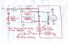
With two or more in series, add equalising resistors across them to ensure the voltage across either one does not creep up over time if the leakage is different between the two.
That should hopefully avoid any problems.
 
Thanks for the reply! Maybe they would be best on the headlight or horn circuit, somewhere there is a fuse. I tried a 2.5 ohm varistor in series with them, thought that may provide some protection however even 2.5 ohms was enough to cause them to be ineffective at filtering out the 6 volt power noise so a fuse would probably bring back the noise. Maybe i'll put them in a metal box? I have some 3 volt zeners that I could use across each one however when I took Bal voltage measurements they were all between 2.2 and 2.5 volts on a 9 volt battery without balance resistors, maybe 100K ohm resistors would ballance? Something high so they could be left with the power on all the time?
 
Last edited:
I have been doing some modeling for a 3rd Prototype that I plan to use on another engine with attention to "Form and Function" and ease of connections.
The plan is to use two circuit boards with the Un-Regulated Power coming up from the bottom board via brass support post that that mount the IC Board on top with Copper Shunt Coils from D+ which will be supported on brass post from the heat sink which will be mounted on 2 hubcap clips with a 6" hose clamp around the generator. The Field Resistor will go on the back side. MOSFET, Output Diode and Field Flywheel Diode on the Heat Sink.
It won't be getting a digital Amp Meter but could. Probably just a Digital Voltmeter so the voltage can be more easily set.
The only wire needed will be the 6 volt switched which I never figured out how to eliminate. DF can go on a brass post while Ground can be made to the Heat Sink and a 10X32 X 2" Brass Screw will carry B+ Output.
Here are the 1st Photos:
ModlingFrontView.jpg
ModlingBackView.jpg
ModlingInsideView.jpg
.
 
UpDate I have the Power Supply Board the Bottom Board done and did a Mock Up with it installed in the photo below. The Power Supply is changed just a little it's now only got one ripple filter network to save space on the board. Also included a 2.5 ohm Thyristor in series with two zeners in series for a 10 volt limit across the Un-regulated output. Only 1 wire will be needed from the bottom board to the top board it's the 6.2 volt reference supply wire. Other wiring will use the post with DF and D+ on post this will clean it up compared with what's now on the car.
ProtoType3MockUp.jpg
 
Update!
_____________________________S D+ R PoT E7 U_________________________
Current Sense
Generator D+
6.2 Volt Reference to high leg of the Voltage Potentiometer
Voltage PoTentiometer Wiper, Lo
E7 Voltage IC pin 7 is the Output to Mosfet Gate
U is the Un-Regulated Supply 5-10VDC
The 2 hookups in the block on the East Side are an available grounds. Ground to the IC board is established through the RT Standoff.
 

Attachments

  • Soldered.jpg
    Soldered.jpg
    831.3 KB · Views: 220
  • Labled.jpg
    Labled.jpg
    646.1 KB · Views: 224
  • HookedUp.jpg
    HookedUp.jpg
    725.5 KB · Views: 214
Last edited:
I suggest you make a clamp to hold each LM311 in place in its socket, otherwise vibration will cause havoc. All cables should have good mechanical anchorages too, to provide strain relief and to prevent fracturing as a result of vibration-induced work-hardening of conductors.
 
"alec_t" That's a good Idea Thanks!
Interesting this one does not have the oscillation problem that 1 and 2 did. Just clean lines as it switches on the oscilloscope!

03/01/2020 Update Note! The Gate Diode is shown with the wrong polarity in the Protype 3 Schematic!
 

Attachments

  • Test Schematic.JPG
    Test Schematic.JPG
    203.1 KB · Views: 277
  • Prototype3_Schematic.JPG
    Prototype3_Schematic.JPG
    854.5 KB · Views: 453
  • Prototype3.jpg
    Prototype3.jpg
    857.8 KB · Views: 243
Last edited:
Hello there,

I just read most of this very interesting thread.
I would like to offer my opinion so please feel free to ignore it.

The basic problem is that the system does not like starting the charge.
This is caused by this regulator struggling to turn on the FET when there is not enough supply voltage to the circuit.

Now, the original mechanical design works the other way round in that the contacts are closed normally and open to turn off the field.

Would it thus be better to consider a depletion type FET instead of an enhancement type?
Those conduct fully until a gate voltage is applied.

That should solve this problem although I have no idea what part number to look at nor can I remember what they are called.

The drive will need to be inverted to drive the gate on when turning the field off.

Best regards
berntd
 
Thanks, it's a good idea, they are called https://en.wikipedia.org/wiki/Depletion_and_enhancement_modes Depleation mode dievices and need to operate at voltages below ground. There may be a way to do it it by adding a circuit to make the -6 volts. Certainly worth exploring.
Since doing all of this I have found out that Bosch and other companies making electronic solid state voltage regulators for negative ground generators use a low power drain circuit that runs off off the car battery all the time even with the key off. They may need 10 ma or something.

Since I have not posted in a while here are some photos of my prototype 1 installed inside a Bosch mechanical regulator housing, Just got installed on a motor and working today:
ERegVWhousingBottom.jpg
ERegVWhousingRT.jpg

ERegVWhousingTop.jpg

Electronic V Reg Housed.jpg

Prototype1 Sch House.JPG

 
Last edited:
I remembered earlier that depletion FETs are actually JugFet or JFet.

There are P-type and N-type JFets so it should be possible to use a positive pinch / turn off voltage (relative to the source) on the P-channel type.

Nice work on the regulator !

Regards
berntd
 
I thought Fairchild would have this but now see they have been absorbed by Onsemi. Pity.

Anyway, there are also depletion mode mosfets that are not Jfet. Advantage there is that the gate is fully isolated.

A quick look has not shown many options. Infineon has some but they are way small.
I have not seen any P-channel types at all.

Hopefully I am not putting you on the wrong path.

Regards
berntd
 
Status
Not open for further replies.

Latest threads

New Articles From Microcontroller Tips

Back
Top