Continue to Site

Welcome to our site!

Electro Tech is an online community (with over 170,000 members) who enjoy talking about and building electronic circuits, projects and gadgets. To participate you need to register. Registration is free. Click here to register now.

  • Welcome to our site! Electro Tech is an online community (with over 170,000 members) who enjoy talking about and building electronic circuits, projects and gadgets. To participate you need to register. Registration is free. Click here to register now.

Audible Alarm circuit

Status
Not open for further replies.

simon Wing

New Member
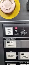
Hi. I need a device to fit over this led to activate a sounder so i know when this machine stops.
Prefer low voltage application maybe 9v Battery. I am happy to make from circuit design or offer a machining job in exchange for complete item. can make enclosure myself
 

Attachments

  • 20220803_124759.jpg
    20220803_124759.jpg
    828.6 KB · Views: 175
This is pretty straight forward, a photosensor on flying leads
to a small box with a ATTINY85 board + regulator + buzzer +
1 cap + battery + push button (unless machine turn off extinguishes
led).

Basic code, use mBlock to generate code :

Note the photosensor is a classic : (connect that to gnd and in series with a R to Vdd, junction to
analog pin 0. R value 1/2 the range photocell experiences when LED off then on. Note you can also
get these in various packages, so look around for what best fits your need. You could also print
a 3D bracket to hold sensor. Lean toward sensor with lower R range values, say into the 1K to 10K
range, as that lowers the value of R needed, which makes the pin lower Z hence less subject to
stray pickup, eg. noise.

1659533598244.png


You will have to adjust PhotoSensorTripV to accommodate the R you use in the divider.
You do this prior to programming in mBlock. Or add a pot, read it on a second analog
pin, and use its value to set the trip V so you can adjust in circuit. Not I did not add code
for Hysteresis in mBlock to eliminate small variances and noise, that would be advisable.

1659533946577.png


The code mBlock produces from above to cut and paste in Arduino IDE :

Code:
// generated by mBlock5 for <your product>
// codes make you happy

#include <Arduino.h>
#include <Wire.h>
#include <SoftwareSerial.h>

float PhotoSensorTripV = 0;
float PhotoSensorV = 0;

void _delay(float seconds) {
  long endTime = millis() + seconds * 1000;
  while(millis() < endTime) _loop();
}

void setup() {
  pinMode(5,OUTPUT);
  pinMode(A0+0,INPUT);
  PhotoSensorTripV = 500;
  // Initialize Buzzer to Off
  digitalWrite(5,0);
  while(1) {
      if(analogRead(A0+0) < PhotoSensorTripV){
          // Buzzer On
          digitalWrite(5,1);

      }else{
          // Buzzer Off
          digitalWrite(5,0);

      }

      _loop();
  }

}

void _loop() {
}

void loop() {
  _loop();
}

Note the analog read yields a reading corresponding to V on the pin as follows -


Then use Arduino to program ATTINY85 board :


1659532729604.png

Note there are cheaper versions of this board, shop it.

To setup Arduino to use / program digispark board -


Use a 5V piezo buzzer to connect to pin 5

1659535382187.png


Note I am showing use of dip package, but small board has regulator and bypass
cap for its ATTINY85.

Regards, Dana.
 
Last edited:
Of course there is always fairly simple network to your phone messaging
solutions using ESP8266.....and using Tuniot (think mBlock but with network
blocks to use for programming). It could both sound an alarm and message
your phone.

Regards, Dana.
 
Status
Not open for further replies.

Latest threads

New Articles From Microcontroller Tips

Back
Top