Hello,
I am surprised that the power switch is only 0.3A, for what potential?
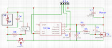
"FDMS8025 FET has a Resistance of 3.5 milliohms" Yes for 4.5V but at 21A! Adding solder connections is probably more.
By convention, the negative pole of a circuit is also named by the term "Ground" is often used to refer to a common reference point for voltage in a circuit. In many circuits, the negative terminal is often connected to ground (0 volts) to provide a reference point to measure the voltage. This ensures the safety and stability of electrical systems.
Why the negative is the ground:
- The ground serves as a return path for the current and a reference point for voltages in a circuit.
- In many DC circuits, especially in battery supplied systems, the negative terminal is generally at a potential lower than the positive terminal. The landing of the negative terminal helps to establish a common reference point for all the components of the circuit.
Well, this is up to you, it's just a convention!
I understood for C6, my concept should be to cut the positive using only a switch able to support 5V and 2A (or more).
I make a mistake on my surface calculation, no real dimension on the size of the PCB sorry, BTW, take a new PCB with full copper on both sides and weigh it, do it for your current PCB and you will have a good idea of weight difference. It's up to you to see if x% of weight increase is less than x% flight autonomy. Same for the increase in traces. (Is the flight weight in pico-gram )
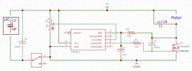
For the time constant, it is determined by R6 (22K) and C5 (100nF) which gives, more or less 2.2 ms, sorry to send you back the question, but why do you put this on PB4 of the UC? The key is probably in your code, but without it, impossible to understand the reason.
My supposition, If PB4 is an input, and PB1 an output, makes it possible to consider this R/C for power on reset (POR), to be sure of the UC state at startup. In this case, are 2.2 ms sufficient or not? The Attiny turns below 100us, it should be enough!
You agree?