Continue to Site

Welcome to our site!

Electro Tech is an online community (with over 170,000 members) who enjoy talking about and building electronic circuits, projects and gadgets. To participate you need to register. Registration is free. Click here to register now.

  • Welcome to our site! Electro Tech is an online community (with over 170,000 members) who enjoy talking about and building electronic circuits, projects and gadgets. To participate you need to register. Registration is free. Click here to register now.

ARM Cortex

Status
Not open for further replies.
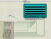
This is what i needed it for
Code:
#include <LPC210x.h>

void GlcdPort(unsigned long Data){
    IOPIN = ((IOPIN & 0xFFFFFF00 ) | Data);
}
void DelayUs(int us) {
	for (; us>0; us--);
}

void DelayMs(int ms) {
	for (; ms>0; ms--)
		DelayUs(1000);
}
int main(void){
	unsigned char x;
	PINSEL0=0x00;
	IODIR=0xFFFFFFFF;

	while(1){
		for(x=0;x<8;x++){
			GlcdPort(0xFE);
			DelayMs(500);
		}
	
	}

}

To create a GLCD Port :D
 
Last edited:
I would define the 0xfffff00 somewhere else (and make it intuitive) so that if you do change hardware configuration, you can just change the definition section and the code will compil and run correctly.
 
heh yeah thanks for tip...

Like a :

Code:
#define GLCDPORT 0xFFFFFF00
.....
.......
void GlcdPort(unsigned long Data){
    IOPIN = ((IOPIN & GLCDPORT ) | Data);
}
 
hey guys another issue now lol How would i set a PIN input/output? Just one like P0.8 ?

I was thinking and got this but not sure. Want advice:
Code:
IODIR = (IODIR & (~(1<<GLCD_CS1 )));
 
Use the set and clear registers whenever you can. They are much 'safer'. You should only use the direct GPIO if you really need to, and it's slower if you are just doing this basic set or clear.

It depends on how the program logic is working, but either:
SET_PORTA_REGISTER = BIT8;
or SET_PORTA_REGISTER = 0x01 << 8;

If you are clearing, just change it to the clear register.

If it's single pin operations, I usually define my pins like this:
Code:
#define lcd7110_BACKLIGHT_PIN  BIT31

then make MACRO's to set and clear them.
Code:
#define LCD7110_LED_ON()       pPIOA->PIO_SODR = lcd7110_BACKLIGHT_PIN;
#define LCD7110_LED_OFF()      pPIOA->PIO_CODR = lcd7110_BACKLIGHT_PIN;

This makes it easier for me to move the code to another processor.

Otherwise your code should work as is if you can't get away with using the set and clear registers. Assuming GLCD_CS1 is a pin number.
 
Im trying to use a 128x64 GLCD and im dieing here lol Im trying to read the data from the port and test it....
Code:
unsigned char GLCD_Read(void){
	unsigned char tmp;
	IOSET = 1<<GLCD_E;
	DelayUs(100);
	tmp = (IOPIN & (~(GLCDPORT)));
	IOCLR = 1<<GLCD_E;
	return tmp;
}
void Wait_Not_Busy(void){
unsigned long DirTmp;
unsigned char CS1Dat;
unsigned char CS2Dat;

	DirTmp = 0xFFFFFF00;
	IODIR=DirTmp;
	
	IODIR = (IODIR & (~(1<<GLCD_CS1)));
	IODIR = (IODIR & (~(1<<GLCD_CS2)));
		
 	IOCLR = 1<<GLCD_RS;
	IOSET = 1<<GLCD_RW;

	CS1Dat = (IOPIN & (1<<GLCD_CS1));
	CS2Dat = (IOPIN & (1<<GLCD_CS2));

	if (CS1Dat==1 && CS2Dat==1){
		IOCLR = 1<<GLCD_CS1;
		while (GLCD_Read()&0x80);
		IOSET = 1<<GLCD_CS1;
		IOCLR = 1<<GLCD_CS2;
		while (GLCD_Read()&0x80);
		IOSET = 1<<GLCD_CS2;
	}
	else{
		while (GLCD_Read()&0x80);
	}

	IODIR=0xFFFFFFFF;


}

EDIT
I just notice you can read a PIN without setting it to INPUT so i scapped the IODIR parts....
Code:
unsigned char GLCD_Read(void){
	unsigned char tmp;
	IOSET = 1<<GLCD_E;
	DelayUs(100);
	tmp = (IOPIN & (~GLCDPORT));
	IOCLR = 1<<GLCD_E;
	return tmp;
}
void Wait_Not_Busy(void){
//unsigned long DirTmp;
unsigned char CS1Dat;
unsigned char CS2Dat;

	//DirTmp = 0xFFFFFF00;
	//IODIR=DirTmp;
	
	//IODIR = (IODIR & (~(1<<GLCD_CS1)));
	//IODIR = (IODIR & (~(1<<GLCD_CS2)));
		
 	IOCLR = 1<<GLCD_RS;
	IOSET = 1<<GLCD_RW;

	CS1Dat = (IOPIN & (1<<GLCD_CS1));
	CS2Dat = (IOPIN & (1<<GLCD_CS2));

	if (CS1Dat==1){
		if (CS2Dat==1){
			IOCLR = 1<<GLCD_CS1;
			while (GLCD_Read()&0x80);
			IOSET = 1<<GLCD_CS1;
			IOCLR = 1<<GLCD_CS2;
			while (GLCD_Read()&0x80);
			IOSET = 1<<GLCD_CS2;
		}
	}
	else{
		while (GLCD_Read()&0x80);
	}

	//IODIR=0xFFFFFFFF;


}

My issue is in ISIS i get errors and nothing on screen....
"Command Write attempted during reset. Write Operation Failed."
 
Last edited:
I'm not reading your code that closely, but if it's like the SAM7, I see two problems here. One is that the read register is totally different from the GPIO setting register. On the SAM7 it's called the Pin Data Status Register. You might want to look for the equivelant on the LPC. Also, if it's the same, the peripheral clock needs to be enabled in order to use inputs at all.
 
I think its just that one ... image below is more informational...

pin-jpg.30664
 

Attachments

  • pin.jpg
    pin.jpg
    71.3 KB · Views: 713
Ya, mine definitely works differently. I have an Output Data Status Register with what I'm currently telling it to output for the output lines, and a Pin Data Status Register with the input values.

I can see, I screwed up with one of your previous questions as well. Looks like you were asking about changing the data direction of a pin. I thought you meant setting the output on/off.

I'll drop out.
 
na stay in lol input is always good. You might learn and teach me some stuff :D

Im going to try some stuff with a simple button and test input/output strategies
 
Last edited:
Ok i think i got it now lol i tried it on button and works nicely... First i was using char instead of long for a pin so causing a overflow type thing....

also i made a function to read a single pin... works nice i think...
Code:
unsigned char GLCD_Read(void){
	unsigned long tmp;
	IOSET = 1<<GLCD_E;
	DelayUs(100);
	tmp = (IOPIN & (~GLCDPORT));
	IOCLR = 1<<GLCD_E;
	return tmp;
}
unsigned char GetPin(unsigned long tPin){
	unsigned long tmp;
	DelayMs(1);
	tmp = (IOPIN & (1<<tPin));
	if(tmp == 0)
		return 0;
	else
		return 1;
}
 
Last edited:
this sucks lol trying to clear the screen and this is what i get:
cls-jpg.30681


This is my full code so far:
Code:
#include <LPC210x.h>

#define GLCDPORT 0xFFFFFF00
#define GLCD_RS  8
#define GLCD_E   9
#define GLCD_RW  10
#define GLCD_DI  11
#define GLCD_CS1 12
#define GLCD_CS2 13

void initGLCD(void);
void GlcdPort(unsigned long Data);
void GLCD_Write_Cmd(unsigned char data);
void ClearScreen(char normal);
void GLCD_Write_Cmd(unsigned char data);
void GLCD_Write_Data (unsigned char data);
void Wait_Not_Busy(void);
unsigned char GLCD_Read(void);
void ClrPin(unsigned long tPin);
void SetPin(unsigned long tPin);

void GlcdPort(unsigned long Data){
    IOPIN = ((IOPIN & GLCDPORT ) | Data);
}
void DelayUs(int us) {
	for (; us>0; us--);
}

void DelayMs(int ms) {
	for (; ms>0; ms--)
		DelayUs(1000);
}

void GLCD_Write_Cmd(unsigned char data){
	Wait_Not_Busy();

	ClrPin(GLCD_DI);
	ClrPin(GLCD_RW);

	GlcdPort(data);

	SetPin(GLCD_E);
	DelayUs(100);
	ClrPin(GLCD_E);
}
void GLCD_Write_Data (unsigned char data){
	Wait_Not_Busy();

	GlcdPort(data);

	SetPin(GLCD_DI);
	ClrPin(GLCD_RW);

	SetPin(GLCD_E);
	DelayUs(100);
	ClrPin(GLCD_E);
}
unsigned char GLCD_Read(void){
	unsigned long tmp;
	SetPin(GLCD_E);
	tmp = (IOPIN & (~GLCDPORT));
	tmp &= 0x000000FF;
	ClrPin(GLCD_E);
	return tmp;
}
unsigned char GetPin(unsigned long tPin){
	unsigned long tmp;
	tmp = (IOPIN & (1<<tPin));
	if(tmp == 0)
		return 0;
	else
		return 1;
}
void SetPin(unsigned long tPin){
	IOSET = 1<<tPin;
}
void ClrPin(unsigned long tPin){
	IOCLR = 1<<tPin;
}
void Wait_Not_Busy(void){
unsigned long CS1Dat;
unsigned long CS2Dat;
unsigned long stat;

 	ClrPin(GLCD_DI);
	SetPin(GLCD_RW);

	CS1Dat = GetPin(GLCD_CS1);
	CS2Dat = GetPin(GLCD_CS2);

	if (CS1Dat==1 && CS2Dat==1){
			SetPin(GLCD_CS1);
			do
			{
				SetPin(GLCD_E);
				DelayUs(1);
				stat = GLCD_Read();
				ClrPin(GLCD_E);
			}while(stat==0x80 || stat==0x10);
			SetPin(GLCD_CS1);
			ClrPin(GLCD_CS1);
	}
	else{
		do
		{
			SetPin(GLCD_E);
			DelayUs(1);
			stat = GLCD_Read();
			ClrPin(GLCD_E);
		}while(stat==0x80 || stat==0x10);
	}
}

void ClearScreen(char normal){
unsigned char x;
unsigned char y;

unsigned char FILL;
	GLCD_Write_Cmd(0x40);	
	GLCD_Write_Cmd(0xB8);

	if(normal == 0)
		FILL = 0x00;
	else
		FILL = 0xFF;

	ClrPin(GLCD_CS1);
	ClrPin(GLCD_CS2);

	for(y=0;y<8;y++)		//page loop
	{
		GLCD_Write_Cmd((0xB8 + y));
		for(x=0;x<64;x++){	//y loop
			GLCD_Write_Data(FILL);
		}
	}

	GLCD_Write_Cmd(0x40);		//go to left side
	GLCD_Write_Cmd(0xb8);		//go to top page

}

void initGLCD(void){
	SetPin(GLCD_RS);
	ClrPin(GLCD_E);

	GLCD_Write_Cmd(0x3F);	
	GLCD_Write_Cmd(0xC0);	

	ClearScreen(0);
}

int main(void){
	PINSEL0 = 0x00000000;
	IODIR = 0xFFFFFFFF;

	initGLCD();

	while(1){

	}

}
 

Attachments

  • cls.jpg
    cls.jpg
    50.3 KB · Views: 783
Last edited:
not sure how your program or the controller works, but isn't RS the same as DI (Data or instruction)? pin P0.8 (GLCD_RS) isn't connected to anything, though it is defined to pin 8 - DI is on pin 11. so maybe you change RS to pin 11 too or fix the program for the inconsistency.

otherwise, try to step through ClearScreen() to see what's going on.
 
Ill try to step through it but RS and DI are the same. My GLCD is using DI not RS. That RS was meant to be RST (reset) i ended up tie-ing it to VCC. i just forgot to take that out :D but it doesnt affect anything i think
 
looks like it is writing to the lcd, except that it does so every other page. what if you hardwire y=0 or y=1 in the clearscreen() and see what happens.

by the way, y should go to 127 (columns), not 64 (rows).
 
i write to both sides at the same time so i only need to write to half the amount of times:
Code:
	ClrPin(GLCD_CS1);
	ClrPin(GLCD_CS2);

	for(y=0;y<8;y++)		//page loop
	{
		GLCD_Write_Cmd((0xB8 + y));
		for(x=0;x<64;x++){	//y loop
			GLCD_Write_Data(FILL);
		}
	}
 
Wow this is funny.. i think its a OSC type issue:

Code:
		GLCD_Write_Cmd(0xB8);
		for(x=0;x<64;x++){	//y loop
			GLCD_Write_Data(FILL);
		}

If i put the 0xB8 in manually it works. if i used B9 it works on line 2. It works but when i put 2 side by side like:

Code:
		GLCD_Write_Cmd(0xB8);
		for(x=0;x<64;x++){	//y loop
			GLCD_Write_Data(FILL);
		}
		GLCD_Write_Cmd(0xB9);
		for(x=0;x<64;x++){	//y loop
			GLCD_Write_Data(FILL);
		}

It doesnt work for line 2... any thoughts?
 
because you used ADC and the column counter is automatically incrementing.

you will need to reset the column counter by pulling it back to column 0 after you go to a new page.
 
Status
Not open for further replies.

Latest threads

New Articles From Microcontroller Tips

Back
Top