AtomSoft
Well-Known Member
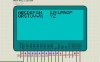
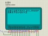
hey  i got another GLCD issue. I know im a pain in the butt.... but when using proteus is it supposed to show like this? I have used the equevilent code on a PIC and it works but for this proteus it doesnt seem to show it right:
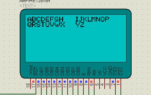
If i change the 63 to a 95 it works fine but there are only 64 pixels on each CSx am i right? so this would have to count to 64
i got another GLCD issue. I know im a pain in the butt.... but when using proteus is it supposed to show like this? I have used the equevilent code on a PIC and it works but for this proteus it doesnt seem to show it right:
Code:
void PutMsg(unsigned char left, unsigned char tLine, unsigned char *msg){
unsigned char side;
screen_left = left;
screen_line = tLine;

		if(screen_left > 64){
			screen_left -= 64;
			SetPin(GLCD_CS1);
			ClrPin(GLCD_CS2);
			side = 1;
		}else{
			SetPin(GLCD_CS2);
			ClrPin(GLCD_CS1);
			side = 0;
		}

		GLCD_Write_Cmd(0xB8+screen_line);
		GLCD_Write_Cmd(0x40+screen_left);

	while(*msg){
		if(screen_left > 63){
			screen_left=0;
			if(side == 0){
				SetPin(GLCD_CS1);
				ClrPin(GLCD_CS2);
				side = 1;
				GLCD_Write_Cmd(0xB8+screen_line);
				GLCD_Write_Cmd(0x40);
			} else {
				screen_line+=1;
				SetPin(GLCD_CS2);
				ClrPin(GLCD_CS1);
				side = 0;
				GLCD_Write_Cmd(0xB8+screen_line);
				GLCD_Write_Cmd(0x40);
			}
		}

		PutChar(*msg++);
		screen_left += 8;

	}

}
If i change the 63 to a 95 it works fine but there are only 64 pixels on each CSx am i right? so this would have to count to 64