Continue to Site

Welcome to our site!

Electro Tech is an online community (with over 170,000 members) who enjoy talking about and building electronic circuits, projects and gadgets. To participate you need to register. Registration is free. Click here to register now.

  • Welcome to our site! Electro Tech is an online community (with over 170,000 members) who enjoy talking about and building electronic circuits, projects and gadgets. To participate you need to register. Registration is free. Click here to register now.

Analysing Power Amplifier circuits-General discussion

Status
Not open for further replies.
here's a simple amp with loads of room for improvement and tweaking. i "built" it on LTSpice in about 10 minutes, and it ran on the first try with no tweaking of component values. there is a lot of room for improvement on this design, and they're all performance tweaks, not changes to just get it working. but as-is, the amp has 0.1% distortion at full output into 8 ohms.

It's the closest we've seen yet! :D

Bootstrap R3, add a Vbe multiplier (instead of the diodes) and it wouldn't be bad. A zobel network on the output would be a good idea as well.

But it certainly looks like a fairly practical design.
 
It's the closest we've seen yet! :D

Bootstrap R3, add a Vbe multiplier (instead of the diodes) and it wouldn't be bad. A zobel network on the output would be a good idea as well.

But it certainly looks like a fairly practical design.

i was going with the simplest possible amp possible. there's a lot of room for improvement. just using a current source in place of R1 and a current mirror to balance the diff amp gets the distortion down to around -60db from the -40db of the unmodified version. a Vbe multiplier eeks out about another -6db (some of the distortion is crossover notch), and a current source in place of R3 brings the distortion down to -80db or so... the TIP31/32 drivers and the 2N3055/2955 outputs are also not the most linear transistors that could be used.

this is a very "standard" amp design, and even without current sources and current mirrors is good enough that Denon, Yamaha, Pioneer and Sony use it currently for their mid-priced receivers with barely any difference from the way i drew it except for a Vbe multiplier in place of the diodes, and the driver transistors being built in to a pair of darlington output devices. also the output choke and zobel to keep it stable with speaker wire capacitances.
 
Last edited:
i was going with the simplest possible amp possible. there's a lot of room for improvement. just using a current source in place of R1 and a current mirror to balance the diff amp gets the distortion down to around -60db from the -40db of the unmodified version. a Vbe multiplier eeks out about another -6db (some of the distortion is crossover notch), and a current source in place of R3 brings the distortion down to -80db or so... the TIP31/32 drivers and the 2N3055/2955 outputs are also not the most linear transistors that could be used.

this is a very "standard" amp design, and even without current sources and current mirrors is good enough that Denon, Yamaha, Pioneer and Sony use it currently for their mid-priced receivers with barely any difference from the way i drew it except for a Vbe multiplier in place of the diodes, and the driver transistors being built in to a pair of darlington output devices. also the output choke and zobel to keep it stable with speaker wire capacitances.

The most important difference on a commercial amp is R3, either bootstrapped or replaced with a constant current source (same thing really). The amp isn't really practical without it, as it severely restricts the power and substantially increases distortion.
 
It's the closest we've seen yet!:p:p:p


Thanks Unclejed613. I will take your circuit into consideration when I do decide to build an amplifier(that would be after the Easter holidays:D).

Just letting you'll know, that the circuits i post are just for analysis. Knowing the purpose of different stages, components and sub-circuits etc. What could be done to improve different stages and make it practical.


Im at the analyzing stages...Designing will come soon:rolleyes:.
 
in addition to the link i provided, i also recommend you read the High-Power Audio Amplifier Construction Manual by G Randy Slone and the Audio Power Amplifier Design Handbook by Douglas Self. both authors provide very well thought out and logical step-by-step approaches to designing amplifiers. i also recommend you read https://www.electro-tech-online.com/custompdfs/2010/03/AN-A.pdf because audio amp and op amp design share a lot of common techniques and challenges.
 
:eek:i spoke too soon its before Easter!, i have to design an amp. Well buh bye analyzing stages.
50V single negative supply into an 8ohm load. Got my specs yesterday. Looking forward to posting "MY" design up and taking criticism. :DEspecially from MR GOODWIN:rolleyes:
Let me get started:)

I do have the book by Douglas:)
 
Last edited:
Just make sure you start with something that has a chance of working :D

Don't worry about the single negative supply, it's pretty meaningless - it's just a single supply, negative or positive is just a question of where you measure from.
 
he's working with a 50V NEGATIVE single ended supply????? why???? nothing about this makes a whole lot of sense....


would anybody be upset if i gave him a Wile E. Coyote Award?????

on second thought, with the weird parameters given, it could be a school project... some prof wants their students to think outside the box (way, way outside the box)..
 
Last edited:
he's working with a 50V NEGATIVE single ended supply????? why???? nothing about this makes a whole lot of sense....

Why?, it makes no difference whatsoever - it's only a modern convention to measure positive with respect to negative, in the early days of transistors the convention was to always measure negative with respect to positive.
 
In telecommunication systems, the positive is always bonded to earth so it's pretty normal to have negative voltages. If it offends you, just change the sign but that can get lead to confusion so it's better to keep it negative.
 
SPECS given: 50v single negative supply, 8ohm load, single transistor input

uhmmmm i tried:D.
 

Attachments

  • -50vsingleSUPPLY8&#11.doc
    97 KB · Views: 282
Many of the transistors will not survive a 50V supply. Select transistors with a higher voltage rating.
C3 is not needed. Then R9 and R10 can be a single resistor.

Q7 needs a load resistor which will help turn off Q6 quickly.
The output transistors need emitter resistors.

The value for C1 is far too small and for C6 is far too large.

The circuit will probably oscillate at a high frequency because it is missing the compensation capacitor that is used on all audio amp and opamp circuits.
 
Many of the transistors will not survive a 50V supply. Select transistors with a higher voltage rating.

yeah, i supposed to check the safe operating area limits for the bjt & see if it will work in the cct.
The max collector current, max voltage it can handle and max power.

Thanks Audioguru
 
Last edited:
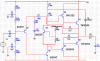
Q6 needs a compensation cap to roll off the gain above 25khz or so as AG has said. Q7 needs to be able to sink the base current of Q6 to ground, and cannot do that as-is. your bias pot should be on the emitter side of the Vbe multiplier, not the collector side. if the pot should fail (not real common, but it does happen) by going open circuit or by the wiper going open from dirt or oxidation, the bias transistor will turn full on, shutting down the bias on the output devices. the amp will still work with some crossover distortion. if a collector connected pot goes open, the bias transistor goes open circuit, running the output devices at or beyond their max current and they will short, and take the driver transistors, and Q6 and possibly Q7 along with them.

you might want to move C6 to where R1 is, R1 to where C1 is, and C1 to where C6 is. the bootstrap cap doesn't have to be very large, but the speaker coupling cap has to be large, and it's best not to have speaker terminals that are live with DC voltage (but designers of class D bridged amps do that all the time without it being much of a safety hazard).

btw, this amp will have a pretty hefty turn-on thump through the speaker when it's turned on, so realize when it does that it's normal for this type of amp.
 
Don't use Word for schematics, use PNG.

There doesn't need to be two capacitors in series with the speaker: C1 isn't needed and will just limit the frequency response to 2kHz.
 

Attachments

  • audio amp..PNG
    audio amp..PNG
    10 KB · Views: 299
C1 isn't needed and will just limit the frequency response to 2kHz.
C1 is needed to block the 25VDC from this single supply amplifier. It should be about 1000uF for -3dB (half power) at 20Hz into the 8 ohm speaker.
 
Don't use Word for schematics, use PNG.

The pic was in bmp and was too large to attach, i tried compressing it in microsoft office manager but the picture quality was poor. Thats why I put it in word.
 
I use Microsoft Paint program to save and change any picture into a PNG.
 
C1 is needed to block the 25VDC from this single supply amplifier. It should be about 1000uF for -3dB (half power) at 20Hz into the 8 ohm speaker.

Yes, you're right, I misread the schematic.
 
The circuit will not work at all because the -50V and 0V lines have no DC connection to ground except through a pair of 200k resistors (R9, R12). The 8 ohm load is returned to ground so all its drive current must flow through these two resistors.

It is not possible that 0V and ground are the same as this would short out R9.

[edit] I didn't notice C3 and C4. There is NO connection between the power rails and GND.
 
Last edited:
Status
Not open for further replies.

Latest threads

Back
Top