fantabulous68
Member
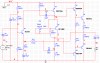
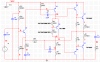
R15 is still connected to the wrong rail. And 640 milli ohms is way too low, no matter where it is.
And the base of Q4 is still connected to the output node. You've just made it a more interesting spiral, but you've left it connected!
I removed R15 (suggested by unclejed613).....
I see the spiral
 , Fixed that now
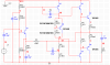

 ?
?
") Done "normalizing";
Done "normalizing";