Continue to Site

Welcome to our site!

Electro Tech is an online community (with over 170,000 members) who enjoy talking about and building electronic circuits, projects and gadgets. To participate you need to register. Registration is free. Click here to register now.

  • Welcome to our site! Electro Tech is an online community (with over 170,000 members) who enjoy talking about and building electronic circuits, projects and gadgets. To participate you need to register. Registration is free. Click here to register now.

Analysing Power Amplifier circuits-General discussion

Status
Not open for further replies.
distortion is usually measured at full output, just below clipping, which would be about 17Vrms. to be on the safe side for asymmetrical behavior, go with 16Vrms or 32W.

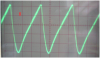
Actually you do it at very low power as well, it's low power where crossover distortion occurs, so it's important to do that as well.
 
you aren't getting 0%THD, what is the vertical scaling of the graph? you need to convert db to percent. it needs to be log scale, 10db/cm to get a more readable display. you also need to change the frequency scaling so you can see the harmonics of your fundamental. the second harmonic is there, but buried in the noise, your third, fourth, fifth, etc... harmonics aren't visible because you used a narrow frequency span.

next time you take a pic of the spectrum analyzer display, turn off the flash.

i used autoscale. on the lower left hand corner it shows THD=0%. It is in %.
I recall wen I started the THD test on the analyser it said frequency/fundamental frequency out of scale or something to that effect; then it displayed 0% THD
 
Last edited:
i'm not sure why you're having such severe slewing problems, but it could be that your input transistor is current starved, and can't keep up with charging the compensation cap (or even the miller capacitance of the voltage amplifier transistor). it's late here, so i'll take a fresh look at it tomorrow.

actually the "stores guy" did not give me a BC556(they didn't have 1), they gave me a BC547 which kept heating up and "dying", it couldn't handle the current SO it was replaced with a 2N2905A which seemed to be the only transistor they had an abundance of.

even the VBE multiplier transistor (BC546B)was replaced with a 2N2219A transistor because they didn't have a BC546B bjt or a good substitute.
 
Last edited:
20db from the signal peak is 1%THD, -30db is 0.1%, -40db is 0.01%, etc... for intermediate values, every -3db is a half, which makes -6db a quarter.
No. Distortion is a percentage of the voltage level, not of the power. When the voltage is half then the current is also half and the power is one quarter.
-6dB is half the voltage, not a quarter. It is 1/4 of the power, not of the voltage.
-20dB is 1/10th which is 10% distortion.
-40dB is 1/100th which is 1% distortion.
-60dB is 1/1000th which is 0.1% distortion.
-80dB is 1/10000 which is 0.01% distortion.
Etc.

Since the 1kHz signal is about only 20mV RMS then the noise is down at about only -30dB. The distortion is probably lower and cannot be measured.
If the signal is increased to about 15V RMS then the noise will be down at about -87dB allowing the distortion to be clearly shown.
 
the THD function didn't work because it couldn't lock on to the harmonics buried in noise.

yeah, it's hard to remember late at night that there is a duality to db scales... AG is right. i often use spectrum analyzers for RF measurements which are in dbm (db milliwatts), and have to switch gears to dbV (db volts). about a year ago i made myself a nice little chart for converting dbV to percent. i'll post it if i can find it.
 
So is this the correct way to carry out s THD measurement?

Change the scaling to db and set the frequency span to 20 Hz-20 kHz, which will include power supply hum in the measurement. Set the reference level to 20dbV (100V), and the signal peak will be around 12dbV. The harmonics will show up at multiples of the signal frequency. With a 1 kHz input, harmonics at 2,3,4,5 kHz etc. can be observed. Measure the harmonics by how far below the fundamental peak they are. When the voltage is half then the current is also half and the power is one quarter. The % THD is the sum of the levels of the harmonics.
-6dB is half the voltage
-20dB is 1/10th which is 10% distortion.
-40dB is 1/100th which is 1% distortion.
-60dB is 1/1000th which is 0.1% distortion.
-80dB is 1/10000th which is 0.01% distortion.
Etc.
 
the amp originally had an input of 100mVp-p and an output 3Vp-p with a frequency of 1.5KHz but now whenever i put it at the same settings its output is 4Vp-p{What would cause this change?}. So i used the 4V p-p wave in the following test:

pic 8

output set at 5V/div
frequency 1.5KHz


The amplitude was adjusted to determine the peak output voltage. From PIC 8 it can be seen that the output=25Vp-p.

is it correct for me to use PIC 8 to determine the peak output voltage?
 

Attachments

  • 8..PNG
    8..PNG
    215.7 KB · Views: 354
I don't know why the output has very high distortion. Maybe some of the electrolytic capacitors are still connected backwards.
Post your latest schematic.
 
I don't know why the output has very high distortion. Maybe some of the electrolytic capacitors are still connected backwards.
Post your latest schematic.

the output capacitor was fixed on the kit and was 4700u not 1mF as on the diagram, the bias stabilising resistors R1 and R2 were also fixed on the kit and were 42E as on the schematic, not all transistors were available so i had to use the type on the schematic

i pointed all the positive terminals of the capacitor to ground and all negative terminals to the -50V supply
 

Attachments

  • clearer thd..PNG
    clearer thd..PNG
    23.9 KB · Views: 333
Last edited:
you used 2N2955 and 2N3055 as input and bias transistors?????????????? why?
the input transistor needs to be a bit faster than a 1Mhz device.... the Ccb is around 100pf in that input transistor, way too high for what you're using it for...
it'll work, but you would be better off with a 2N2905 as the input transistor and a 2N2219 as a bias transistor.

are you sure your compensation cap is 33pf and not 330pf? it's an easy mistake to make especially since the value marking of some manufacturers is a 3 digit code, where 330 would be a 33pf cap (digit, digit, multiplier), and 331 would be a 330pf cap, and other manufacturers mark a 33 on a 33pf cap and 330 on a 330pf cap. the best way to tell the difference is to measure it.

with a 330p cap instead of a 33p cap you will get slew rate limiting at 1khz and running the output voltage almost rail-to rail just as your scope trace shows
 
Last edited:
Your amplifier won't work properly with R15 removed. I said before that it should be about 10k ohms.
It also won't work with those wrong transistors.
 
the guy from stores gave me a flat yellow cap with no markings on it and said it was 33pf but later i realized that the cap value was higher and replaced the compensation cap with 33pF
 
yeah but i had to use those components since stores didnt have a good substitute.
 
the 2955 hasn't enough gain to act as an input transistor (it will work, but not work very well). and using a 3055 as a bias transistor doesn't seem a bad idea at first, because it can easily be mounted to the heat sink and and would provide very good thermal tracking, but the large surface area is also a large capacitance to ground in a part of the circuit that should be a high impedance node (this part of the circuit is bootstrapped to increase the impedance).
 
the 2955 hasn't enough gain to act as an input transistor (it will work, but not work very well). and using a 3055 as a bias transistor doesn't seem a bad idea at first, because it can easily be mounted to the heat sink and and would provide very good thermal tracking

Quite the opposite, it will provide poor thermal tracking because of it's large mass, so it would track very slowly and poorly.

but the large surface area is also a large capacitance to ground in a part of the circuit that should be a high impedance node (this part of the circuit is bootstrapped to increase the impedance).

No, it's bootstrapped to increase current drive during peaks that side - bootstrapping is used to increase impedance on input circuits, not on this.
 
In addition to increasing the voltage peak, the bootstrapping makes the collector resistor appear as a higher resistance which increases the voltage gain of the transistor.
 
In addition to increasing the voltage peak, the bootstrapping makes the collector resistor appear as a higher resistance which increases the voltage gain of the transistor.

Yes, but that's not it's main reason - without bootstrapping or a constant current source it makes a pretty feeble amplifier, much higher distortion and much lower power.
 
Yes, but that's not it's main reason - without bootstrapping or a constant current source it makes a pretty feeble amplifier, much higher distortion and much lower power.

two sides of the same coin, actually, increasing the impedance and increasing the voltage swing.
a current source is probably out of the question as the OP's local parts shop seems severely limited in their supply of suitable transistors.
 
Status
Not open for further replies.

New Articles From Microcontroller Tips

Back
Top