Continue to Site

Welcome to our site!

Electro Tech is an online community (with over 170,000 members) who enjoy talking about and building electronic circuits, projects and gadgets. To participate you need to register. Registration is free. Click here to register now.

  • Welcome to our site! Electro Tech is an online community (with over 170,000 members) who enjoy talking about and building electronic circuits, projects and gadgets. To participate you need to register. Registration is free. Click here to register now.

AC coupling

Status
Not open for further replies.

eng1

New Member
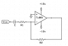
I am using a bipolar supply with an inverting op amp. The input is a sine wave (5 V p-p) and its frequency can be as low as 10 Hz. I'd like to add a cap to eliminate the DC offset of the sine wave. The input resistance is 10 kohm.
I could change this value and use a 1 uF non polarized capacitor... instead (and this is the question) if I add a 22uF elec. cap, how should it be oriented?
Thanks

EDIT: the sine wave swings between -2.5 and +2.5 V.
 
Last edited:
As it's a bi-polar supply, and a zero referenced signal, there should be no polarising voltage across the capacitor - so either way should be fine, although it's preferable to arrange for a polarising voltage across electrolytics.
 
Please post a schematic.
 
Hero999 said:
Please post a schematic.

It's a simple voltage inverter. R1 = 10k ohm. The input signal is a sine wave swinging from -2.5V to 2.5V ideally, fmin=10 Hz. I need a high value for C, without changing R1, so I must use an elec. cap.
 

Attachments

  • c1.png
    c1.png
    1.6 KB · Views: 405
As it's a split supply, and the input signal is referenced to zero volts, why do you need a capacitor at all?, simply DC connect it!.

Or do as I answered earlier!.
 
Nigel Goodwin said:
As it's a split supply, and the input signal is referenced to zero volts, why do you need a capacitor at all?, simply DC connect it!.

Or do as I answered earlier!.

After your answer I was asked to post a schematic.
BTW this is an input stage and I don't know if other people will apply a zero referenced sine wave as I do... I didn't write this thought.
If I add two diodes (without R2) in the feed-back path to make a zero crossing detector, any DC offset (small or large) is unwanted.

If I can't predict the polarity of the DC offset, do I need to use a non polarized capacitor?

Thanks
 
Last edited:
Sorry, you're right. I thought to get a general answer for non-inverting configuration.
 
Since you want to capacitor-couple the input, then why is the input impedance so low as 10k ohms which requires an electrolytic capacitor for good low frequency response?
The opamp has an extremely high input impedance with the FETs on its inputs, so use 100k or 1M rersistors. Then you can use a film non-polarized coupling capacitor with a lower value but still have good low frequency response.
 
To minimise the effect of biasing currents you should connect the +input to ground via a resistor with the same value as R1 and R2 in parallel.
 
Hero999 said:
To minimise the effect of biasing currents you should connect the +input to ground via a resistor with the same value as R1 and R2 in parallel.
That is to balance the opamp's input bias currents. But the TL081 opamp he is usung has FET transistors at its inputs which don't have bias current.
 
Status
Not open for further replies.

Latest threads

Back
Top