MrDEB
Well-Known Member
designing a Statue of Liberty lapel pin for the 4th of July 2023'
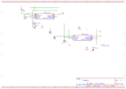
have two similar schematics for a pulsating led (white 3mm led) but the capacitors are electrolytic caps that are larger than 3mm in diameter (have only 1/4 inch height restriction. THINKING of maybe using a titanium cap or? need to order parts but the capacitor size?
both of the schematics are basically the same.