Continue to Site

Welcome to our site!

Electro Tech is an online community (with over 170,000 members) who enjoy talking about and building electronic circuits, projects and gadgets. To participate you need to register. Registration is free. Click here to register now.

  • Welcome to our site! Electro Tech is an online community (with over 170,000 members) who enjoy talking about and building electronic circuits, projects and gadgets. To participate you need to register. Registration is free. Click here to register now.

7 seg counter+pulsating circuit

Status
Not open for further replies.

richyyo

New Member
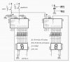
well i made a circuit with 2, 7 segment display working by 2 4026b counting chips. the circuit also has a pulsating buzzer. but after i tested it out the buzzer didnt work and the counter only works some of the times. i checked if anything was loose but i couldn't find anything. could anyone just check out the circuit and see if there is anything wrong?
(circuit diagram on doc.)
thx a lot
 

Attachments

  • circuit_512.doc
    99.5 KB · Views: 205
4026 is made in CMOS technology and must connect every used inputs (clock in, reset, etc) at ground (GND/-) or + thru resistors (100..470k) and unused inputs directly at GND or V+ (see https://www.electro-tech-online.com/custompdfs/2006/01/cd4026b.pdf )

PS: for each 4026 outputs (a,b,c, d, e, f, g) must conect serial resistors (470-560 ohms) at display inputs ...
 

Attachments

  • 4026.jpg
    4026.jpg
    53.7 KB · Views: 316
Status
Not open for further replies.

Latest threads

New Articles From Microcontroller Tips

Back
Top