Continue to Site

Welcome to our site!

Electro Tech is an online community (with over 170,000 members) who enjoy talking about and building electronic circuits, projects and gadgets. To participate you need to register. Registration is free. Click here to register now.

  • Welcome to our site! Electro Tech is an online community (with over 170,000 members) who enjoy talking about and building electronic circuits, projects and gadgets. To participate you need to register. Registration is free. Click here to register now.

555 Timer question, circuit attached

Status
Not open for further replies.

adown

Member
Hi Everyone, I put an amplified ipod system on my Harley and was getting noise through the amp while plugged into a store bought 12V to USB adapter to charge. I built a 5 v reg with filters that work great, but I want to switch off the charger while riding and as soon as I turn off the ignition, I want it to charge for 2 hours. I put a monostable 555 because it will work of the pulse of the ignition turning off and making the normally closed contacts to 12 volt, but not be affected by the 12 volts being there for days. Am I right on this. Thanks for your help.

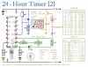
PS: the values show on the filter portion are not actual. It is just 2 pi filters. Ferrite beads and caps
 
The maximum allowed value for the timing resistor for the bipolar LM555CM is 10Meg. Maybe you can have a higher value on the CMOS version.

The leakage of a 100uF capacitor is likely higher than the current that can be supplied through 50Meg, so the timing is suspect.

Where do you get a 50Meg resistor?

You are pushing it to get a two hour delay using a 555...
 
Last edited:
Hi MikeMi, Thanks for your reply, I didn't think about the current through 50M ohm. I just used an online RC calculator and standard resistor values. I guess 50M isn't standard? The LM555CM is the only timer I had in my program. I just want to keep my Ipod from draining my motorcycle battery, although highly unlikely.

Maybe a 4060B timer circuit would be better. Could I replace the relay in this picture with my regulator/filter circuit?

Thanks, adown
 

Attachments

  • 4060B timer.png
    4060B timer.png
    11.7 KB · Views: 242
The 4060 has an RC oscillator, followed by a binary counter. It is useful to make long timers as shown in your link. The red PNP transistor is on until the delay elapses. The collector will be at battery potential -Vce(sat) while it is on. It should source enough current to run your Ipod via the regulator and noise filter. The purple diode D1 stops the clock after the delay elapses. You would want to replace the reset push-button with a diode (cathode toward the timer) from the ignition circuit in the bike.

btw, are you sure you need the L-C filter if you feed the output of the Voltage Reg to the Ipod?
 
Last edited:
Thanks MikeMi, the PI filter is filtering out the charging noises i think. I havn't tried it without though. I did try a store bought power port to USB adapter and the noise was tremendous, so a good friend told me to use the filter on the output and throw one on the input for good measure.

Wouldn't I just want to remove the entire reset circuit. The way I understand it, the circuit will reset when power is removed (I might be wrong). I didn't pay any attention to the rc circuit on the reset. I don't understand why it's there. Didn't add it to the drawing yet.

Voltage to the circuit will only be applied when my bike is off(through normally closed relay contacts). When It's running, my ignition will energize the relay and will remove voltage from the circuit.

The Ipod will only take 100-500mA, and from what I've read, it will regulate itself at 100-200mA.

I am going to put it all together inmy sim program. I'll post the drawing. I really appreciate all your help. I know just enough to be dangerous. Thankfully parts are cheap,,well, except for the Ipod.

Thanks, adown,

EDIT I dont have that timer in multisim. I could draw it, but I can't simulate it.
 
Last edited:
You want the reset applied to the circuit until the moment you turn the key off when parking the bike. That is the action that starts the 2 hour timing cycle. Or did I misread your intent?

If you believe in IC Voltage Regulators like I do, then they will make the L-C filter redundant.
 
Last edited:
You have it correct, but as shown in my EDIT above with the drawing, I was planning on removing all power to the circuit with the bike running. I will study the data sheet and pin functions more. Thanks for your help, adown
 
You have it correct, but as shown in my EDIT above with the drawing, I was planning on removing all power to the circuit with the bike running. I will study the data sheet and pin functions more. Thanks for your help, adown
Why bother with the relay. The timer and charger will draw about the same power than the coil in the relay while the bike is running. Why can't you charge the Ipod while listening to it? What guarantees that two hours is enough to charge the Ipod?
 
I could run the 5v charger/ filter as is, but at 3/4 volume I still have some slight audible noise. When I unplug the charger, it goes away. That is the reason for wanting to remove the charge circuit when running. Most people probably wouldn't notice it, but I've spent a lot of time and money to put this system on and I'm kind of a perfectionist. It probably happens on all Ipods, just not noticeable until amplified 400 watts. The Ipod also can't just be unplugged to take in and charge, it requires a little disassembly. I did that on purpose to prevent a grab and go, or having to take it with me every time.

Apple says an Iopd will charge from 0 to full in 3 hours on a USB outlet, which run around 100mA. The 7805 runs 500mA, but the Ipod is internally regulated.

Thanks again
 
Mike, I know this is old, but you were right about the relay. After doing some more studying, I ditched it in favor of keeping the reset applied while the bike is running( ignition), and keeping the circuit on battery. I know, just like you said in post #6. It just takes me time to understand. I am still trying to figure out if the 557 transistor and the 1N4148 will handle the regulator circuit. Here is the final, I think.
 
Status
Not open for further replies.

Latest threads

Back
Top