Continue to Site

Welcome to our site!

Electro Tech is an online community (with over 170,000 members) who enjoy talking about and building electronic circuits, projects and gadgets. To participate you need to register. Registration is free. Click here to register now.

  • Welcome to our site! Electro Tech is an online community (with over 170,000 members) who enjoy talking about and building electronic circuits, projects and gadgets. To participate you need to register. Registration is free. Click here to register now.

555 timer help

Status
Not open for further replies.

thekyguy11

New Member
Hello

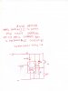
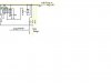
I'm building a project that will utilize a 555 timer. I purchased one, and a bread board, and I have been experimenting with all different circuits. Instead of confusing everyone with how the entire project will work (believe me, its confusing) I'll just explain how i need the 555 timer to work. And I'll add that I have successfully built all of the circuit examples I can find online, all of which work, but none of which work for my application.

-It needs to not trigger when powered up.
-When power (or ground, whichever it takes to make it work) is applied to pin 2, I need it to still do nothing.
-When power(or ground) is removed from pin 2, then I want the timer to begin (which will add power to pin 3). When the timer runs out, i need it to remove power from pin 3 (without re-triggering itself!). And that's it. Also, I do know how to control the length of time the timer runs for.

I hope this makes sense to someone. I've seen and re-created so many different 555 circuits, and I either can't get it to not re-trigger itself, or it triggers on power up, or the trigger has to be a pulse, which doesnt help.

Any help is appreciated!
 
i think this one will do

sorry upside down
 

Attachments

  • Image2.jpg
    Image2.jpg
    136.6 KB · Views: 360
Thanks rjvh for the quick response! Unfortunately, I've tried that one before. The problem is that the timer is triggered when s1 is closed, which I can't have it do. Then, if s1 remains closed it re-triggers over and over. I just built your drawing again, just to be sure, and it does as I described.

I need it to be powered up with s1 open, not trigger when s1 is closed, then trigger once s1 is opened again.
 
I was going to say, if it requires a second 555, or just one 556 (I would prefer just one 556 over two 555's) that's fine. Here is an example of one that comes close to working for me...

**broken link removed**

Circuit 2 almost works, but I need it to keep pin 3 low when s1 is closed, then go high when s1 is re-opened.
 
I attached a little example of what the pin2, pin3 relationship would be. Wouldn't actually be 1 second, in my case, but you get the idea.
 

Attachments

  • Example.GIF
    Example.GIF
    2.8 KB · Views: 234
thekyguy11 said:
I have no idea what you are talking about, lol. What is that V3 thing?

That looks like it's just a screenshot of a simulator. V3 would be a signal source for the simulated circuit.


Torben
 
I just keep looking at that schematic and trying to understand it all, but I just don't. Do the resistance values you gave mean anything? Or can I just use different ones? I know the R3 and C2 in your drawing are the time period, but what are the rest? I'll build it and see what happens, but I don't have all those resistance values on hand.
 
I built that drawing as close as I could get it, and it doesn't really do much. I just have an LED connected at pin 3. When I power up the breadboard, the led comes on right away. Then it doesn't really ever turn off. When I unplug the breadboard, the led stays lit for a little under a second and then turns off.

Maybe it will help if I explain exactly what my project is...here it goes....

My father and I are building a vegetable oil setup for his diesel truck. It will work like this.

Filtered, used cooking oil from a restaurant will be poured into an auxiliary tank on the truck. The tank will be heated by engine coolant circulating through a coil in the tank. As the truck warms up, so will the veg oil. There will be a temp sensor in the veg oil tank (probably just a simple thermistor) that, once the appropriate temp has been reached, will switch the auxiliary fuel pump on and the diesel pump off. The truck will then be running on straight veg oil.

Now here is where the 555 comes into play, it will work like a turbo timer. Once the truck is shut off, I want the diesel pump switched back on and the veg oil pump switched back off and the truck to remain idling until the timer runs out and shuts the truck off. The 555 timer will simply turn on a relay that will put power to the "ON" wire of the truck that normally sees power when the truck is "ON", despite the ignition being switched off. The difficult part for me here is that I don't want the "turbo timer" part to run unless the veg oil pump has been running, otherwise there is no point in leaving the truck idle after the user has shut it off.

Here is where I'm at with the project...

Using this setup... **broken link removed** I am able to make everything work almost exactly the way I want. In this setup, pin 3 goes high only after the veg pump comes on and remains high and begins the timer after the veg pump goes off. This is because I was using the power feed to the veg pump to close and open s1.

I am beginning to feel like I need to draw up my full schematic for this to all to make sense... I'll try that...
 
There already are a few companies that sell a system like this... https://www.greasecar.com/ is just one example.

Attached is my schematic I drew up in paint (couldn't find my digi cam and I don't have a scanner). My issue is that as soon as the veg pump comes on it turns on the relay that puts 12v to the "key on" wire, which is fine because it would make for a seamless transition into the timer mode after the key is turned off. But, because the relay that switches between the two different fuel pumps uses that same "key on" wire, it will never switch back to diesel. One last thing is that I do NOT want to cut the "key on" wire to put a diode in, especially because of the amperage that goes through that wire. I want the installation of the wires to kinda tap into the factory wires, not cut them apart (except the fuel pump wires, those don't matter so much).
 

Attachments

  • Project.JPG
    Project.JPG
    10.6 KB · Views: 225
Last edited:
blueroomelectronics said:
Running a diesel vehicle on the road with anything but diesel fuel (that has the road taxes) will get you a nice fine.
That depends on where you live, here in the UK you can make a certain amount or biodiesel providing you don't sell it to anyone.
 
should I look into using a micro-controller for this instead? I don't really know the first thing about them, but I'm willing to learn.
 
Status
Not open for further replies.

Latest threads

New Articles From Microcontroller Tips

Back
Top