Continue to Site

Welcome to our site!

Electro Tech is an online community (with over 170,000 members) who enjoy talking about and building electronic circuits, projects and gadgets. To participate you need to register. Registration is free. Click here to register now.

  • Welcome to our site! Electro Tech is an online community (with over 170,000 members) who enjoy talking about and building electronic circuits, projects and gadgets. To participate you need to register. Registration is free. Click here to register now.

555 inverter design- doesnt work- please help

Status
Not open for further replies.

illconductor

New Member
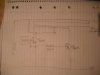
Gday. well i designed this peice of garbage and worked on it all day. just doesnt work.

basically if i put leds in place of the transformer they alternate, but put a tranny there and no go. just seems like not enough current, but as i understand it the 555 will output 6 volts and 200 ma, so shouldnt that be plenty to saturate the transistors?

the 100k is there to stop the bases turning eachother on.

would be very greatful for any help thanks.
 

Attachments

  • DSCF0155.JPG
    DSCF0155.JPG
    1 MB · Views: 846
The PNP transistor has its C & E swapped. The 100k resistor is way too big to sink enough base current from the PNP transistor. You might find it works better if you connect another 555 after the first 555 as an inverter & use its output to drive the second NPN transistor (replacing the PNP).
 
mmm thanks mate, o yeah sorry i drew the pnp wrong the c and e are swapped. theres no problem with having the load on the emitter side of the pnp is there?

i was just flicking through these forums and someone said as a rule of thumb in switching the base current should be 1/10 of the collector current, recon thats right? im starting to think the 555 is not very good for inverters as it only has one output.

just a side question-thought.... i have 2 types of transistors, tip42c, and tip 122
the tip 122 is darlington type hfe 1000, the tip 42c is not -hfe 100.

now i found that if you touch the battery with one hand and touch the base with the other hand the non darlington tip42c will let current pass, the tip 122 will not let current pass in the same fashion. now i thought that darlington tranistors ( with hfe like 1000) were more sensitive. it seems back to front.. any ideas?
 
You have another serious problem: the NPN transistor has no base resistor, so the output of the 555 is clamped by the base to emitter diode. As mentioned, the PNP is upside down, and the 100K is too high. Put a 1k resistor from the output pin of the 555 to the base of the NPN and the base of the PNP.

btw- this is not a very good design for a lot of other reasons, but doing the above should at least make it work long enough for the transistors to overheat and blow up ;)
 
thanks mate, dont really understand what u mean by clamped but i suppose you mean doesnt work :) . and il try a 1k resistor on the output.

one thing tho, im thinking the tranistors would overheat from over current to the tranny windings. how would you limit this? to whatever say 3 amps for this particular npn
 
Just to be clear, you need two 1k resistors, one for each base, both of which are connected to pin 3 of the 555.
 
The base-emitter of the BD681 caused over-current in the output of the 555 and probably blew it up. It needs a resistor from the output of the 555 to the base of the BD681 to limit the current.
Replace the BD682 with another BD681 and drive it with a logic inverter which could be a second 555.

Then you will have a square-wave low power inverter without any voltage regulation.
Why bother?

Why are you making a square-wave inverter?
Why are you making it with low current transistors?
 
Hi,

before you carry on frying transistors how about frying your power supply?

Here is a simple inverter circuit using MosFets to power the transformer.

Output frequency = input frequency/4.

The BUZ11 can make 33A at 25deg/C - much to play with.

Boncuk
 

Attachments

  • Inverter.gif
    Inverter.gif
    9.9 KB · Views: 3,131
  • 50Hz.gif
    50Hz.gif
    61.3 KB · Views: 888
thanks alot guys ill start playing with this stuff, i think the 2x 555 is a good idea, but ill just use a 4047 i think to get to alternate pulses. never knew you could over current a 555 , so a 1k is needed there thanks. and that last one is a bit over my head but thanks.
 
actually, could anyone explain why there is both an npn and a pnp connected to the gate, looking at the mosfet, they are connected to the 0v . There will be a positive and negative pulse from the pnp/npn section wont there?...or perhaps mosfets triggger on both pos and neg pulses?
 
actually, could anyone explain why there is both an npn and a pnp connected to the gate, looking at the mosfet, they are connected to the 0v . There will be a positive and negative pulse from the pnp/npn section wont there?...or perhaps mosfets triggger on both pos and neg pulses?
The gate-source of a Mosfet has a high capacitance that takes a fairly high current to charge and discharge quickly so that the Mosfet switches quickly. If the Mosfet does not switch quickly then it spends time ramping slowly and getting very hot.
The NPN transistor has enough current to quickly pull the gate high to turn on the Mosfet quickly. The PNP transistor has enough current to quickly pull the gate low to turn off the Mosfet quickly.

But since this inverter operates at such a low frequency then the transistors do not do much.
 
thanks, just a side question-thought.... i have 2 types of transistors, tip42c, and tip 122
the tip 122 is darlington type hfe 1000, the tip 42c is not -hfe 100.

now i found that if you touch the battery with one hand and touch the base with the other hand the non darlington tip42c will let current pass, the tip 122 will not let current pass in the same fashion. now i thought that darlington tranistors ( with hfe like 1000) were more sensitive. it seems back to front.. any ideas?
 
The tip122 has integrated resistors (see diagram) as well - this means there will be a minimum current required to turn it on.
 

Attachments

  • tip122.gif
    tip122.gif
    1.7 KB · Views: 459
All transistors have a minimum current to turn them on.
The TIP122 has base-emitter resistors to quickly turn it off.
 
ok thats cool thanks, so even tho the tip122 is darlington, at low current that high gain effect is negated? i get that i think , but why does the tip42c which is not darlington opperate on such low current ie, through my skin.?
 
The high gain of a darlington allows its input base current to be low.
The TIP42 needs a high base current that is 1/10th its collector current.

Your skin does not have a rated resistance so testing things by touching them is meaningless.
 
ok thats cool thanks, so even tho the tip122 is darlington, at low current that high gain effect is negated?
Due to the shunting resistors forming a voltage divider with your skin resistance the base voltage doesn't get high enough to turn on the internal transistors if the current is too low.

i get that i think , but why does the tip42c which is not darlington opperate on such low current ie, through my skin.?
Because the tip42c doesn't have the shunting resistors, the base voltage can rise to the required level for conduction.
 
brilliant thanks alot.

if anyone doesnt mind another question.here i go

i just hooked the output of my astable 555 into antother 555 opperating as a not gate.

the output of 555 no1 is through a 10k resistor to the input of 555 no2 (1k was too small) the output of 555 no2 then goes to a tip122 via a 1k resistor the tip122 is switching the secondary windings of a 16v:240v transformer. the transformer doesnt produce a decent output like this, ive tryed changing the resistors from 100r to 1k to 10k to 100k still cant get good swiching current. ( its a 400ma secondary, so i have no idea what the impeadance of it would be but when i connect the secondary directly to 6v it produces a good output)

thanks.
 
If you can't show a schematic of your circuit then we don't know what your circuit is like. Maybe you connected the TIP122 upside down. We don't know if the 16V or the 240V winding of the transformer is the primary or the secondary. How can two power transistors drive a transformer winding that is not center-tapped?

What is "a decent output"? What is wrong with its output?
 
Last edited:
Status
Not open for further replies.

Latest threads

New Articles From Microcontroller Tips

Back
Top