Continue to Site

Welcome to our site!

Electro Tech is an online community (with over 170,000 members) who enjoy talking about and building electronic circuits, projects and gadgets. To participate you need to register. Registration is free. Click here to register now.

  • Welcome to our site! Electro Tech is an online community (with over 170,000 members) who enjoy talking about and building electronic circuits, projects and gadgets. To participate you need to register. Registration is free. Click here to register now.

555 inverter design- doesnt work- please help

Status
Not open for further replies.
a decent output is one that feels like the same shock i get from the secondary as i do with the 6 v battery hooked up to the primary.( its scientific haha)

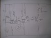
the am only using one tip122 at the moment becuase i dont have a centretapped transformer. the idea is to have two tip122 and a ctapp tranny.

the orientation of the transitor is bce , and i know that from expeimentation and the datasheet

originally the 240 was the primary and 16v the sec, now its the otherway around.

thanks
 

Attachments

  • DSCF0156.JPG
    DSCF0156.JPG
    1,020.8 KB · Views: 201
You must not connect the "TIP122 NOR" to the input of the second 555 because the input high voltage of the TIP122 is only about 1.5V and then the input of the 555 will never go high.
The output of the first 555 can drive the TIP122 through a 1k resistor.
The output of the first 555 can directly drive the input of the second 555 without a resistor. Your resistor value was too high and was in the wrong place.
 
so your saying that if the tip122 was connected directly to the input of the second 555 then the high output of the first 555 will get drained to ground via the base and therefore not trigger the second 555?

so the question is the output of a 555- is it enough to saturate the tip122 and if so, what resistor if any should i use at the output before the base

so far ive used 100r 1k 10k 100k and none produce full current through e-c (tranny primary )
 
its always fun, but im trying to make a small inverter. so im trying to get maximum continuous current from the transistors which is 5A
 
The maximum peak current of a TIP122 is 8A (for no longer than 8ms).
In your square-wave inverter they each conduct for 10ms if your mains is 50Hz.
Maybe they do not have enough base current to conduct 8A.
 
Status
Not open for further replies.

Latest threads

Back
Top