Continue to Site

Welcome to our site!

Electro Tech is an online community (with over 170,000 members) who enjoy talking about and building electronic circuits, projects and gadgets. To participate you need to register. Registration is free. Click here to register now.

  • Welcome to our site! Electro Tech is an online community (with over 170,000 members) who enjoy talking about and building electronic circuits, projects and gadgets. To participate you need to register. Registration is free. Click here to register now.

555 Dark Detector Circuit Help

Status
Not open for further replies.

Suraj143

Active Member
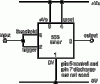
I have this circuit. When dark is applied to the LDR, the output LED will light up.

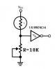
I tried with many opamp’s but I’m not satisfied with their performance.

I need a 5V output when dark is applied. Also it must be very sensitive. The output must not float in between 0V to 5V. It must directly show logic 5V or 0V.

Can you please see this circuit whether it’s ok or not.
 

Attachments

  • 555 Dark Detector.JPG
    555 Dark Detector.JPG
    14.6 KB · Views: 2,642
I would use a Schmitt Trigger.

You can make one either from an Op Amp (or Voltage comparitor) or use a CMOS Hex Schmitt Inverter such as the 40106.

I suggest that you post the circuit of the Op Amp one that you are not happy with so we can analyse it and suggest imprevements.

What was the issue that you were not happy with?
 
I need to operate from 5V.

When I use an op amp when in ambient light the output led goes dim not giving 5V or 0V. I used a hysteresis too but still the problem is there.

Here is the circuit i replaced LM358 instead of 741.
**broken link removed**

But this 555 circuit the led wont dim its giving 5V or 0V.
 
Didn't you look at the datasheets for the 555, the 741 and the LM358?

The output low of an ordinary 555 is +0.1V when its load current is low. Its output high is +3.6V.

Many 741 opamps don't work if their supply voltage is less than 10V.
If you found a 741 that works with only 5V then its output low is +1.2V and its output high is +3.8V wothout load current.

The LM358 works when its supply is as low as 3V.
With a 5V supply its output low is 0V or +1.0V depending on its load current.
Its output high is +3.8V without load current.

You need a Schmitt trigger or a circuit with hysteresis to switch quickly when it gets dark.
 
Hi audioguru thanks for your very useful information’s. Do you have some Schmitt trigger circuits? I have never built one like that.

Thanks
 
About 45 years ago I made Schmitt trigger circuits with 2 transistors. Look in Google. Cmos Schmitt trigger inputs on inverters and gates are used now.
 
What about making a Schmitt trigger by using 555 like in the attachment.

What I need is to add the LDR & transistor circuit to this circuit to give 5V or 0V in the output.
 

Attachments

  • Inverter.gif
    Inverter.gif
    4 KB · Views: 653
If you want it to operate on 5 Volt, there are at least 3 solutions.

1. use a 74HC14 Hex Schmitt Trigger IC. This has enough current source and sink capability to drive a LED. This solution requires the least number of components. But don't neglect to connect the unused inputs to gnd.

2. Use a Voltage Comparitor IC such as the LM311 configured as a Schmitt Trigger. It has a transistor output that will drive the LED, see the data sheet for details.

3. Use an Op Amp that can operate from a single 5V supply and use an N channel MOSFET (such as the 2N7000) to drive the LED.

Options 3 & 3 have the advantage that you can set the hystersis according to your need. Whereas, in the case of option 1, the hystersis is set inside the IC.
 
Suraj143 said:
What about making a Schmitt trigger by using 555 like in the attachment.

What I need is to add the LDR & transistor circuit to this circuit to give 5V or 0V in the output.
There is a Schmitt Trigger inside the 555. But the problem is that the hystersis is set inside the 555 to about one third of Vcc. This is probably too wide for your situation.
 
Hi ijcox thanks for your suggestions. I like your first method.

The 74HC14 Hex Schmitt Trigger IC.
What about the input side? I need only a V/R & LDR is that right?

& the output I can connect to a led via resister?

Thanks
 
Suraj143 said:
I need to operate from 5V.

When I use an op amp when in ambient light the output led goes dim not giving 5V or 0V. I used a hysteresis too but still the problem is there.

Without looking at the Op Amp's data sheet, I suspect that the Op Amp does not switch to a low enough voltage to switch the transistor off. That's why I suggested you use an N channel MOSFET in a previous post.
Here is the circuit i replaced LM358 instead of 741.
**broken link removed**

There is no hystersis in this circuit. You need a resistor from the output of the Op Amp to the + input. But it won't operate at 5 Volt.

But this 555 circuit the led wont dim its giving 5V or 0V.
I don't understand your last sentence. It does not make sense.
 
Suraj143 said:
Hi ijcox thanks for your suggestions. I like your first method.

The 74HC14 Hex Schmitt Trigger IC.
What about the input side? I need only a V/R & LDR is that right? Yes

& the output I can connect to a led via resister? Yes
Thanks
However, as I said in my original post, the hystersis may be too wide since it is set inside the IC.

You could possibly solve this by applying some negative feed back.

This would require another Schmitt Trigger (you have 5 spares in the IC) with its input connected to the output of the first one. Connect a resistor from the output of the second to the input of the first. I have not done the calculations, but I expect that this will reduce the hystersis.

EDIT

I made an error in the above.

You don't need a second Schmitt, just connect the feedback resistor from the output of the first to its input. set the value of the resistor to give the hystersis that you need.
 
Last edited:
ljcox said:
There is no hystersis in this circuit. You need a resistor from the output of the Op Amp to the + input. But it won't operate at 5 Volt.

Hi ijcox when I’m testing the LM358 I added hysteresis to the wrong pin.

I replaced the Rh (feedback resister) to the output pin & to the (-) inverting pin which is connected to the LDR.

I’ll give a try to place that resister to the out & non inverting pin.

But the original circuit gives that to the inverting pin.
 
Suraj143 said:
Hi ijcox when I’m testing the LM358 I added hysteresis to the wrong pin.

I replaced the Rh (feedback resister) to the output pin & to the (-) inverting pin which is connected to the LDR.

I’ll give a try to place that resister to the out & non inverting pin.

But the original circuit gives that to the inverting pin.
Hystersis requires positive feedback. So the feedback resistor must go from the output to the + input.
 
Ok now I got it.I’ll look after adding a Hystersis sure this time it won’t dim the LED when it is placed in ambient light.

Earlier I have added a negative feedback from that I didn’t get a progress.
 
Negative feedback reduces the voltage gain of an opamp and makes it slowly follow the changing resistance of the photo-detector.
Hysteresis is a little amount of positive feedback to make the output have a fast snap action.
 
Failed in both cases

Hi sorry to trouble again.

I failed in both cases the LM358 circuit & 74HC14 one.

In LM358 I added a 150K resister from the output pin to (+) non inverting pin.
But still in ambient light the output LED is dim.

After I tried with 74HC14 circuit in that the output LED is all the time is on. No sensing.

Attachment has the circuit I use. In both cases the LDR & 10k resister is vise versa.

Here is the link of LM358 circuit it has 741 but i put 358.
**broken link removed**
 

Attachments

  • 74HC dark detector.JPG
    74HC dark detector.JPG
    4.4 KB · Views: 288
Suraj143 said:
Hi sorry to trouble again.

I failed in both cases the LM358 circuit & 74HC14 one.

In LM358 I added a 150K resister from the output pin to (+) non inverting pin.
But still in ambient light the output LED is dim. I thought I explained this issue in a previous post. It is because your transistor is not turning off fully.

That's why I suggested you use an N channel MOSFET.

However, a red LED would give you enough off set. Connect it is series with the base resistor. It does not matter if it glows or not.

After I tried with 74HC14 circuit in that the output LED is all the time is on. No sensing. The change in voltage is not large enough. That is why I said that you would have to reduce the hystersis. See below.

Attachment has the circuit I use. In both cases the LDR & 10k resister is vise versa.

Here is the link of LM358 circuit it has 741 but i put 358.
**broken link removed**

You don't seem to understand Schmitt triggers.

Have you studied the data sheet of the 74HC14?

The one I have shows that the TYPICAL threshold levels are 2.5 Volt and 1.6 Volt at a Vcc of 4.5 Volt.

That means that, for a typical IC with a 4.5 Volt supply, the input voltage has to rise to at least 2.5 Volt in order to make the output go from high to low and then, it must go down to less than 1.6 Volt in order to make the output go from low to high.
 
What an expression now only I understood what’s the meaning of threshold voltage.

Ijcox don’t scold me for that LM358 circuits output I connected the base of the 2n2222 via 33ohm resister. Now I have to use a 2N7000 n channel one as you said.
But do I need a base resister for that?
 
Status
Not open for further replies.

Latest threads

Back
Top