Continue to Site

Welcome to our site!

Electro Tech is an online community (with over 170,000 members) who enjoy talking about and building electronic circuits, projects and gadgets. To participate you need to register. Registration is free. Click here to register now.

  • Welcome to our site! Electro Tech is an online community (with over 170,000 members) who enjoy talking about and building electronic circuits, projects and gadgets. To participate you need to register. Registration is free. Click here to register now.

+/-3.5v to 0-100k resistance conversion circuit help please!

Status
Not open for further replies.
djpubba said:
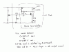
No it should shift the minimum voltage from the pot by 0.5V thus giving you about 1 V min as you want. it will also shift the max voltage a bit.

I tested it before saying that. It doesn't shift by any significant value. It just crops it to 1v. So I get 1.0v far left as desired but center and far right are the same as before the change -- no shift.

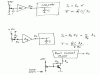
Not knowing what I'm doing, I decided to try making a resistor ladder between 0v and +5v to get +2.5v and fed that into the -5v pin on the Vectrex controller so that my input voltage range would be +2.5 to +5 instead of 0 to +5, hoping that would shift my output voltage range. It did something completely different than I expected. It gave me +1.3v on the far left, +1v center and +1.6v far right. :shock:

Ron's point re the LDR delay and the open loop issue is relevant. So it may not work very well. I had not looked at a LDR spec, so missed this point.

Judging from how the game controls with the LED/LDR circuit, the response time is more than adequate for proper gameplay. It's just in the wrong spot -- the right side of the controller.

I'll still try Ron's circuit.
What LDR circuit are you testing?
 
djpubba said:
Ron H said:
If you build the level-shifting circuit, buy a dual op amp and do it this way.

Which op-amp will run on +5? Will the LM324 work?
As I said in a previous post, you need a rail-to-rail I/O op amp, which LM324 isn't. Tell me where you are getting your parts and I may be able to suggest one. Can you use SMT parts? A thru-hole rail-to-rail may be hard to find.
I also have a schematic of the LDR feedback scheme that Len proposed, if you want to look at it. It uses three r-r I/O op amps, so you might want to get a quad if you build it.
When you have unused op amps, you should keep the unused one(s) active by connecting the output to the inverting input (voltage follower configuration) and connecting the noninverting input to a voltage that is within the common-mode input voltage range. This can be GND in a dual-supply system, or it can usually be the noninverting input node of another, used op amp in the package. You need to do this because some (all?) multiple op amp chips have an internal biasing circuit which is common to all op amps in the package, and floating inputs can upset this circuit.
 
MYSTERY SOLVED. I stupidly assumed that the time in the computer is T = k.C.I where I is the output current from Ron's circuit. But, I belatedly did the maths and it is T = k.C/I so it is no wonder the results are non linear.

So the solution is to use a current amp rather than a trans conductance amp. Then the input current is 5/Rp where Rp = R3 + the pot resistance. R3 is as in Ron's circuit. The current amp could be as drawn or an op amp with current mirror inputs.

The "-5V" connection can be left open since there will be no current through the R4 resistors.
 

Attachments

  • djpubba1.gif
    djpubba1.gif
    44.2 KB · Views: 472
ljcox said:
MYSTERY SOLVED. I stupidly assumed that the time in the computer is T = k.C.I where I is the output current from Ron's circuit. But, I belatedly did the maths and it is T = k.C/I so it is no wonder the results are non linear.

So the solution is to use a current amp rather than a trans conductance amp. Then the input current is 5/Rp where Rp = R3 + the pot resistance. R3 is as in Ron's circuit. The current amp could be as drawn or an op amp with current mirror inputs.

The "-5V" connection can be left open since there will be no current through the R4 resistors.
Len, I need to think about that, but don't you still have a min-to-max ratio problem?
 
Ron H said:
Len, I need to think about that, but don't you still have a min-to-max ratio problem?
No, I don't think so. The range is set by Ai and the centre can be set by a DC off set current. However, Ai needs to be <1, ie. about 0.02, so this may be a problem.

Note that Rp ranges from 2.9k to 12.9k according to my calculkations from Tim's measurenents.

So if Ai = 0.02, then T = k.C 100 Rp
 
Ron H said:
Len, I need to think about that, but don't you still have a min-to-max ratio problem?
No, I don't think so. The range is set by Ai and the centre can be set by a DC off set current. However, Ai needs to be <1, ie. about 0.02, so this may be a problem.

Note that Rp ranges from 2.9k to 12.9k according to my calculations from Tim's measurenents.

So if Ai = 0.02, then T = k.C 10 Rp which is roughly equivalent to the 100 k pot.

So perhaps we need an NPN current mirror in lieu of the amp I drew.
 
What do you guys think of this?

**broken link removed**

I already have four DS1666-100's, which look very similar to the MAX5160's used there. Would this be simpler? Looks like I'd need a comparator and a oscillator. I'm sure I have oscillators around I can grab, but what's a comparator?
 
djpubba said:
What do you guys think of this?

**broken link removed**

I already have four DS1666-100's, which look very similar to the MAX5160's used there. Would this be simpler? Looks like I'd need a comparator and a oscillator. I'm sure I have oscillators around I can grab, but what's a comparator?
Digital pots are quantized, which means they have a finite number of steps. The highest resolution ones I have seen are 10 bits, which means they have 1024 steps. Your apparent pot position would possibly dither randomly by one step, which in the case of a 100k pot would be about 100 ohms. I don't know if this would be acceptable or not. :?:
 
Hmmm. The DS1666-100s I have are 7 bit... 128 steps. Might be too jumpy. 10 bit might be okay, though.

The pot position on the Vectrex controller already jumps all over the place at small increments because you're fighting against the centering springs to hold it in one spot. That makes it incredibly far from steady already, Teddy. ;)
 
I don't think you need to explore that path. I have to go out for half an hour, when I return, I'll do some calculations on the option I outlined earlier.
 
Ron H said:
djpubba said:
Ron H said:
If you build the level-shifting circuit, buy a dual op amp and do it this way.

Which op-amp will run on +5? Will the LM324 work?
As I said in a previous post, you need a rail-to-rail I/O op amp, which LM324 isn't. Tell me where you are getting your parts and I may be able to suggest one. Can you use SMT parts? A thru-hole rail-to-rail may be hard to find.

I've got Fry's, Vetco and Radio Shack near me. SMT'd be last resort, but my deadline is very near, so I'll take anything that works and is fairly simple.
 
djpubba said:
Ron H said:
djpubba said:
Ron H said:
If you build the level-shifting circuit, buy a dual op amp and do it this way.

Which op-amp will run on +5? Will the LM324 work?
As I said in a previous post, you need a rail-to-rail I/O op amp, which LM324 isn't. Tell me where you are getting your parts and I may be able to suggest one. Can you use SMT parts? A thru-hole rail-to-rail may be hard to find.

I've got Fry's, Vetco and Radio Shack near me. SMT'd be last resort, but my deadline is very near, so I'll take anything that works and is fairly simple.
The only one I can find quickly is National's LM6132. It's a dual in an 8 pin DIP. I don't know if Fry's will have it, and I live in the hinterlands. The nearest Fry's is probably 700 miles away. I could look for more, but it would be a crap shoot.
 
I'm having a problem with the constraints imposed.

Does the computer have a -5V supply available? That would help me.

Forget this question, I reviewed your first post and thew answer is no.

So I'll look into +5 to -5 converters.
 
I have tried various options and I think the attached will work.

It combines my idea of making the result linear and Ron's level shifter.

The op amp CA3130 will operate from a single 5V supply and the input voltage can be as low as -0.5V.
 

Attachments

  • djpubba2.gif
    djpubba2.gif
    44.7 KB · Views: 596
CA3130 crosses to NTE930. Hopefully someone will have that in stock.

Excuse my ignorance, but which of Ron's schematics is the level shifter?
 
Status
Not open for further replies.

Latest threads

Back
Top