ljcox said:
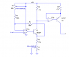
I have looked at your previous posts and realise I did not answer this question. You can shift it by about 0.5 V by inserting a diode in the "-5V" connection. Anode to the "-5V" and cathode to gnd.
If necessary, you could connect a pot (20 k or greater) in parallel with it to allow fine adjustment.
This seems to just chop off the lower .5v instead of shifting it.
No it should shift the minimum voltage from the pot by 0.5V thus giving you about 1 V min as you want. it will also shift the max voltage a bit.
I'm fairly optimistic that if we can shift the range of the original LED/LDR circuit so that far left gives 1v, center gives 1.25v and far right gives 1.5v, it'd work.
That's what the diode is intended to do.
A refresher on what I'm getting now versus what I'd like:
Existing LED/LDR circuit:
Left - 1.6v (150 deflection)
Center - 1.1v (880 deflection)
Right - .7v (940 deflection)*
*The deflection stays the same from .7v-1.0v, leading me to believe the LED doesn't start emitting photons until about 1.0v.
Yes, I have not looked at the spec for an infrared LED, but a red one needs at least 1.6 V. So 1 V sounds reasonable.
Target:
Left - 1.6v (150 deflection)
Center - 1.25v (500 deflection)
Right - .9v (940 deflection)
ljcox said:
Do you reckon that'll have the range I'm after?
Ron's point re the LDR delay and the open loop issue is relevant. So it may not work very well. I had not looked at a LDR spec, so missed this point.
Thanks,
Tim