I hooked up a 100k pot and it works as expected.
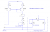
Edit: So... from the measurements I've taken, the magic area that gives me the movement range I want happens when the LED is getting between 1.0v and 1.5v. Center will be 1.25v. Right now my circuit gives me from .5v to 1.5v. So how can I shift it so that I get 1.0v to 1.5v going to the LED instead of .5v to 1.5v?
Edit: So... from the measurements I've taken, the magic area that gives me the movement range I want happens when the LED is getting between 1.0v and 1.5v. Center will be 1.25v. Right now my circuit gives me from .5v to 1.5v. So how can I shift it so that I get 1.0v to 1.5v going to the LED instead of .5v to 1.5v?