Continue to Site

Welcome to our site!

Electro Tech is an online community (with over 170,000 members) who enjoy talking about and building electronic circuits, projects and gadgets. To participate you need to register. Registration is free. Click here to register now.

  • Welcome to our site! Electro Tech is an online community (with over 170,000 members) who enjoy talking about and building electronic circuits, projects and gadgets. To participate you need to register. Registration is free. Click here to register now.

250 watt grid tie inverter build

Status
Not open for further replies.
works

that's my first post after reading whole thread dozen times.
I'd thank you tcmtech for excellent guide!
I actually built one on my desk with biggest available transformer -> sinking cca 2A at 12V power supply and power meter shows 35W.
Got wings!
Got questions!
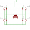
I'd like to use old 3-phase 3hp 230Vac motor (till waiting for material to make own 12V windings). It is clear that I need rectifier. And with stronger wind also DC voltage will rise.
So I obviously need something in between. Or not?
 
Tcm, You used caps in H-bridge to dump switch off current. Do you have tested diodes instead? Using bridge rectifier paraller with transformer conduct switch off current back to power supply.
It looks more efficient way and put less stress to h-bridge parts. It may reduce harmonics too?

Comments?
 

Attachments

  • gti2.png
    gti2.png
    4.9 KB · Views: 2,588
Take a closer look at the first schematic I posted. they are part of the IGBT devices! They are what bypasses the switching devices and let the spike get absorbed by the capacitor.
What your saying is true it does help protect the switching devices and it already incorporated into the design.
 
you won't be able to opend the files unless you have Altium Designer (I think)?

There are some PDFs though.
 
Doh. I missed those.:eek:

Basic analog power system with IR2110's driving a standard H bridge. It dont get much simpler and more efficient than that! ;)

I dont see any AC line filtering though.
But at 100 watts it wont put out too much noise any way.
Nice clean layout of the actual unit.
The control systems seem a bit over complicated but thats just my opinion.
I would still consider it a good reference point any way! :)

The more people who test, experiment and build then post their work the better! :)

Get as many possible design concepts out on the Internet as possible. Somebody will start building them cheaper when there is enough information available! ;)
 
What are you all talking about the .sch and .brd are eagle files and it has a pdf and a txt list of parts what can't be opened
 
Last edited:
My computer didnt like them and wont open them. Its all I can tell you.

Im not a computer person. If I click on it and it wont open thats a far as I get.
 
If you have eagle you can open them they look good all but the avr has to be a pic for me lol
 
If it's Eagle then you'll need to download it; it can be found using Google.:D
 
Here's another one

Hi guys,

here's another one, now more neatly designed I think. The article seems to have been published only today:

Link to **broken link removed**

Please also see attachment.
 

Attachments

  • fig_03.gif
    fig_03.gif
    76.9 KB · Views: 4,480
Hi Guys is it possible to modify a normal inverter to a grid tie inverter?
Thanks

No.

And those who have the brains to figure out how to do it with a Class D audio amplifier and a Phased Locked Loop have the brains to know releasing the schematics would be irresponsible.
 
And those who have the brains to figure out how to do it with a Class D audio amplifier and a Phased Locked Loop have the brains to know releasing the schematics would be irresponsible.

Not really. Rather its just a needlessly complicated way to do it when there are much simpler and easier to build circuits that can do the same thing. ;)

The biggest problem with modifying off the shelf inverter units is simply that there are so many ways the are built that there is no universal hack that would work on all of them. Each brand and model is rather uniquely designed onto itself thus making every grid tie conversion something that would have to be specifically designed for each brand and model anyone tried to use. :(

Mostly grid tie co-gen is about saving money in the end which ultimately comes down to doing it as simple and cheap as effectively possible.

On DIY designs the end safety and responsibility are up to the builder and implementer of the end product not the designer and poster of the schematics. :p
 
Last edited:
not to mention the fact that you aren't going to be diy'n a current mode inverter from an off the shelf voltage mode modified sinewave inverter if you're asking for help on a forum.

i mean, its possible but you'd have to have an ac line current sensor and full control over that H bridge.


here's a question: do ul 1741 grid tie inverters attempt to push a sine wave into the grid (as in they produce harmonics) or do they just follow the line?
with all the computer loads in the cities, it seems to me the grid would welcome the third harmonic produced by cheap and dirty diy grid tie inverters.:D
its not like the backfeeding the grid is even a concern, even if 10% of the grid was sub 10kw inverters, power goes out the grid goes down.
 
Last edited:
Status
Not open for further replies.

Latest threads

New Articles From Microcontroller Tips

Back
Top