Continue to Site

Welcome to our site!

Electro Tech is an online community (with over 170,000 members) who enjoy talking about and building electronic circuits, projects and gadgets. To participate you need to register. Registration is free. Click here to register now.

  • Welcome to our site! Electro Tech is an online community (with over 170,000 members) who enjoy talking about and building electronic circuits, projects and gadgets. To participate you need to register. Registration is free. Click here to register now.

250 watt grid tie inverter build

Status
Not open for further replies.
Control system Component Function Basics II.

This GTI build up Thread is intended for residants of the united states only! Should you decide to build and use such a device as this you may be breaking laws and can face possible fines, and or jail and prison time for it. Should you chose to build such a device as this and intend to use it for saving energy in your home or dwelling you are still breaking the law. Beware you are considerd a pirate Grid tie operation, which is considered illegal in many countries! ;)

CONTROL CIRCIUT FUNCTIONS.

Here are the primary control functions you should be using in your GTI.

OUTPUT MONITORING.

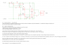
The AC side MUST have a minimum of at least the peak line voltage high-low monitoring circuit with the time delay. This tells the GTI if it’s safe to actually connect to the AC line or not. It must override all DC side control functions!
The AC side MUST also have line frequency monitoring and it is set up like the AC side peak line voltage monitoring function as well. It watches the line frequency and will not let the GTI actually connect if the line frequency is too high or to low. It too must override all DC side control functions!
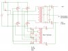
INPUT STAGING

This is still recommended but however it is optional depending upon the GTI design setup you have chosen. The control transformers can be turned on and off using a window comparator circuit with a delay timer in order to make the system more efficient. This optional control circuit will turn on the control transformers a few volts below when the GTI actually connects to the line. This will allow the power transformer and power circuits to be already running and will make the connection to the AC line nearly seamless. With the time delay the GTI can disconnect when the input power is too low for powere feedback but not actually shut down until the time delay has been run. This allows the GTI to idle during short dips in the input power without actually turning off every time.
Again this greatly smoothes out the connecting and disconnecting with the AC lines and saves on standby power, but is purely optional.

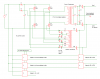
MULTI LEVEL SWITCHING.

This is also an optional control function. This will make it possible for the GTI to run two or more voltage input stages. This allows the power transformer to switch between high and low input voltage ranges automatically if it has the extra taps on the primary and or secondary windings.
This control circuit is the same as the window comparator circuits used by both of the other DC control sections. It will allow the power transformer to run on the low voltage input up to the amp limit of the transformers windings and then switch to the high voltage input. This makes a very good power scavenger function as it allows the GTI to pick up the lowest possible input power it can and still be able to feed it back into the AC lines.
The high range function allows the GTI to then use the more powerful and more efficient input power available without needing to run at low volts and high amps.
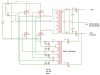
It your power transformer has a tap on the line side of it another control circuit can also be added to give it one more range also. This would give it a 3 stage capability!
Just make sure that when switching taps from one to the other that one tap is turned of before the other is connected!
 
Last edited:
Power & Control Transformer Circuit

This GTI build up Thread is intended for residants of the united states only! Should you decide to build and use such a device as this you may be breaking laws and can face possible fines, and or jail and prison time for it. Should you chose to build such a device as this and intend to use it for saving energy in your home or dwelling you are still breaking the law. Beware you are considerd a pirate Grid tie operation, which is considered illegal in many countries! ;)

This is the actual circuit layout for the power and control transformers.

The control transformer is shown as a single unit with 4 isolated secondary taps. However 2 transformers with dual isolated secondaries or 4 single transformers will work too. The control transformer assembly is a voltage source only circuit so very small transformers can be used.

The small round dots on the power and control transformers designate the phase relationship between each winding.

TR1 and TR2 control the actual transformer connection with the AC line.
TR3 and TR4 are optional for a single line source system. They are only needed for a dual line American style 120/240 volt system.

TR1 -TR4 are actually solid state relays but can be mechanical relays instead if the drive signal from the control circuit is designed to work with them.

D1 -D8 are 15 volt 1w Zener diodes. These are to prevent the switching devices from getting too high of gate voltage. They should be mounted as close to the switching devices as possible!

Q1 - Q4 can be single high amp switching devices or several single units in parallel at each corner of the H-bridge circuit.
Q1 - Q4 can also be a pair of half bridge units as well.
The actual components and layout are up to the builder.

X1 and X2 are opto coupler driven SCR's but they too can be replaced with mechanical relays if the control circuit is designed to work with them.

See schematic attached below.
 

Attachments

  • Basic  GTI Power Circuit.jpg
    Basic GTI Power Circuit.jpg
    118.8 KB · Views: 5,873
Hey all,

Just thought I'd pop in and say I'm still alive.

I just got my SSI-200W and tore it down without even powering it up. Some *VERY* clever stuff in there, but I have to say this:
It will never, ever, not in a million years, be OK'd for UL1741. The THD alone would take a big redesign to pass. I'll power it up tomorrow and try to take some scope shots of the AC current driven back into the grid, but it's got a cheap-'n-dirty self-biased H-bridge to do the polarity swap right at the grid interface. Effective, if you don't mind a 0.8ms dead time and a 30v step chopping off the zero-crosses of your sine wave. But alas, we US-ers are stuck with these pesky regulations that say a sine should be at least mostly a sine.

Other than that, it seems like a very capable device and the topology is freakin brilliant. The brains are an Atmega8 running at 16MHz. They must flash it after assembly because the full programming port is right there populated in the board. Haven't checked if code protect bits are set, but it would be total amatuer hour if they were not, so I'm not expecting to read out their ROM or anything.
 
The brains are an Atmega8 running at 16MHz.

That sounds cool and all, But I can still kick its butt with all analog! :p

What frequency does analog run at? Oh wait thats right, I does not need one! :D

How about some pictures? I think we all would like to have a look! :)
 
I doubt I could do much from the hex to ASM from the Mega8 if it doesn't have the lockbits set but I wouldn't mind a copy of the hex if you can dig it out, eeprom too.

You should be careful tcm you'd be surprised what you can do with a micro controller given solid power electronics and analog support. AVR makes some nice chips that have PLL's for their timers that allow 8bit PWM at 100+khz. Throw in a good fet and some filtering and you can have nearly a pure sinewave inverter. I'd be curious to see the scope view's of the inverter too.
 
I am just teasing him!:p

you'd be surprised what you can do with a micro controller given solid power electronics and analog support.
some filtering and you can have nearly a pure sinewave inverter

But still how much code and procesing does it take to make a sine wave that an LC tank can do naturaly? :confused:
And dont those filters at the end work like LC tanks to clean up that digital "nearly almost sort of looks like a signwave" wave form? :confused:

I do understand the versitility and adaptibility of digital control and I do use it more than I ever show here on this forum.
But I am just more of an analog man myself!

To me digital control seems to most often beused by theorists that are trying to make something act the way they think it shoud and not actualy letting it work the way is would natualy.

Digital is very fussy about working enviroment and conditions and is not forgiving to the unknown and odd variables that come with being in that enviroment or working conditions.

I am just an analog fan myself! I view things from a practicality aproch.
I dont see the point of overcomplicating things if its not nessisary.

Digital has its place and so does analog.
 
Last edited:
Well the digital/analog war seem to have already started. But I have to say, the verdict on the SSI-200 is.... Analog!

My guess is the micro is just to do the input/output shutoff requirements and the MPPT, the heart of the beast is an old unitrode UCC3806 push pull.

-First pic (overall_small.jpg) shows what is required to reverse engineer any device. One multimeter and said device, disassembled.

-Second pic (top_small.jpg) gives a better view of the top of the board. All your power components are here. DC input on the right, AC output on the left.
Starting from the right top, you can see the 4 mosfets (75v) that make up the push-pull and the big yellow push pull transformer.
Next in the signal path is at the bottom, two big toroid inductors and two diode bridges (the 8 devices at the bottom edge). Here your push pull output is rectified to HV DC (kinda).
Last in the signal path is the top left, the 4 mosfets (800v) that make up the H-bridge. They output to another smaller toroid inductor which then pipes into the smaller common mode transformer who connects to the line.

-Third pic (bottom_small.jpg) shows the belly of the beast. Atmega8 up in the upper right hand corner, and UCC3806 in the middle right. They tried to grind off the part numbers, but did a half-ass job. The only one they actually ground off successfully was the little SO8 next to the UCC3806. But alas, that IC has a bevelled edge which only comes from one manufacturer - duh! Trace power and ground, and discover that it can only be an op-amp. It's used to buffer the sine wave sensed off the grid and send it back to the control circuitry.

Good things: Push-pull is very clever and CHEAP. Output H-bridge is truly brilliant, first I've seen of it's kind. And overall topology is simple yet effective - the mark of a durable, reliable device.

Bad things - grid is not really isolated from the input (fatal flaw) because the sine wave feedback runs right into the op-amp and back to the low voltage side. One lightning strike to your power pole and your inverter, panel, charge controller, and maybe yourself, are fried. Also, H-bridge is sloppily implemented and does not give clean switching so THD is well outside the spec.

Next victim: the SWEA, if it ever comes. Beware the lowest-cost ebay seller, he does not seem to have the devices he's selling and is not at all straightforward in his communication about it. Excuses and lies, mostly.
 

Attachments

  • overall_small.jpg
    overall_small.jpg
    128 KB · Views: 1,769
  • top_small.jpg
    top_small.jpg
    207.8 KB · Views: 1,746
  • bottom_small.jpg
    bottom_small.jpg
    262.3 KB · Views: 2,137
Can't call it a war if there is no other side to challenge! :D

From what I've been experimenting with over the years I can't honestly say that anything but good old analog and a big heavy iron core transformer can be beat for rubustness, reliability, cost, and just all around simplicity! They can take a vicious electrical beating and still keep on going. Plus just by design it can give a good sinewave output even with less than ideally matched parts! :)

However for the control and monitoring end I do like digital control! I do actualy use a PLR system on my bigger designs.
All its doing is monitoring the system and doesn't actualy have any control over the wave forms. Its just a good babysitter and lets the analog do what its does best. The only time it actualy interacts with the analog side of the system is during a stage change or an out of range shutdown.
Even then all it gets to do is on/off control over the input connection, output connection or voltage range changing devices.

In my opinion they both work best when used together. Let the analog do the power handling grunt work, its what it does best! Then deligate the logic of what to watch and what to do about it to the digital.

Digital has got the brains but lacks the natural muscle and robustness that analog packs when it comes to doing the power work. :)
 
Line Frequency Monitor Circuit.

This GTI build up Thread is intended for residents of the united states only! Should you decide to build and use such a device as this you may be breaking laws and can face possible fines, and or jail and prison time for it. Should you chose to build such a device as this and intend to use it for saving energy in your home or dwelling you are still breaking the law. Beware you are considered a pirate Grid tie operation, which is considered illegal in many countries!

Thanks for sitting through a long delay in my getting more schematics done. The weather warmed up and the snow melted so I have been spending most of my time working outside again. ;)
I hope you have been able to get the power handling circuit built and somewhat tuned up and tested to some degree by now. :)

Here is the schematic for the actual frequency monitoring circuit. This is based on an actual working unit, However I did leave several component values blank due to the large differences in voltage, frequency and possible component substitutes that may be encountered with this build.

I did give you a basic reference legend that will give you the reasons why for each component.

So. Sorry, but this circuit does require you to do some math and a little component matching of your own! :eek:

And dont overlook that this is a line powered circuit, So use extra caution while testing and tweaking.

If you need a clearer understanding of how this circuit works I have references to its functions in earlier posts.
 

Attachments

  • Line Frequency monitor Circuit.png
    Line Frequency monitor Circuit.png
    23 KB · Views: 5,269
Last edited:
Peak Line Voltage Monitor Circuit.

This GTI build up Thread is intended for residents of the united states only! Should you decide to build and use such a device as this you may be breaking laws and can face possible fines, and or jail and prison time for it. Should you chose to build such a device as this and intend to use it for saving energy in your home or dwelling you are still breaking the law. Beware you are considered a pirate Grid tie operation, which is considered illegal in many countries!

Here is the schematic for the actual peak line voltage monitoring circuit. This is based on an actual working unit too, However I did again leave several component values blank due to the large differences in voltage, frequency and possible component substitutes that may be encountered with this build. Blah, blah, blah. :D

I did give you a basic reference legend again that will give you the reasons why for each component.

So. Sorry again, but this circuit does require you to do some math too and a little component matching of your own! :eek:
(yea I cut and pasted to save some time):p

This is nearly the same circuit as the frequency monitoring circuit so if your using a four comparator IC you can easily just add this to the circuit and not need to build two separate monitoring systems.
The original ones I built were independent of each other. (different design and development times)
However there is no reason that these two could not be combined onto one IC and one power source.

I could have morphed these together onto one schematic too, but this way makes it easier to read and follow.

And dont overlook that this is still a line powered circuit, So use extra caution while testing and tweaking. :)

If you need a clearer understanding of how this circuit works I have references to its functions in earlier posts.
 

Attachments

  • Peak Line Voltage Monitor Circuit.png
    Peak Line Voltage Monitor Circuit.png
    26 KB · Views: 2,249
Last edited:
GTI Function Block Schematic

This GTI build up Thread is intended for residents of the united states only! Should you decide to build and use such a device as this you may be breaking laws and can face possible fines, and or jail and prison time for it. Should you chose to build such a device as this and intend to use it for saving energy in your home or dwelling you are still breaking the law. Beware you are considered a pirate Grid tie operation, which is considered illegal in many countries!

Well this is what a complete GTI schematic looks like! Well sort of.
I condensed the control circuits down as simple function blocks to show how they are connected in the actual GTI design.

But this should give you an actual conceptual look at how they interact with the system and with each other.

I provided basic block reference numbers so you could have some idea of what each block represents in the actual circuit. And the notes are for reference to misc other things as well.

The DC side control circuits can be powered off of the actual DC source if its minimum low range voltage is high enough.
This wont work for systems that have less than a 12 volt low range.
So for the lower voltage higher current designs a standard step down transformer and power supply will be needed in order to drive it from the line side power. Being a low powered circuit, the transformer can be very small.

The AC side control circuits must be electrically isolated from the control signal that they interrupt.
The actual AC control circuit design could be modified to run off a small transformer and be added to the DC control circuits if needed.

The whole point of the long write ups and circuit descriptions is to give you a basic understanding of what each component does. This will make changing the circuit to suit your own design or needs simpler and easier.
None of the actual component sizes or circuit layouts are set in stone.
As long as you keep the design parameters in mind there are countless ways of modifying and controlling this system! ;)

If your good with Microcontrollers, toss the whole analog control system out and go all code! If you want greater efficiency with the switching circuits toss the control transformer and go with all Mosfet/IGBT driver IC's!
If you have actually built a full analog GTI and have it working and understand why it works, what ever you change or modify is entirely up to you! ;)

Just remember the safety and control rules and stay within the laws and regulations of your area. :)

Here is the actual notes from the block diagram. The picture seems to wan to convert to a blurry image for some reason.

TR1 -TR4 are solid state relays.
Mechanical relays can also be used but control system circuits may need to be modified to work with them.
X1 -X2 are SCR opto coupler triggered.
Mechanical relays can also be used but control system circuits may need to be modified to work with them.
BLOCK UNIT DISCRIPTIONS.
1: system standby circuit.
Powers up the control transformer before connection to the lines.
Also serves as standby/off control for DC side of the system.
2: Stage one control.
Turns on X2, TR1 &TR3 for standby/run mode changes
3: Stage two control.
Turns on X1 for low high mode changes.
4: AC line side monitoring.
Overrides signal to TR2 & TR4 preventing control system activation if line conditions are wrong.
Also overrides signals to TR1 &TR3 preventing main power system activation if line conditions are wrong.
Can also overide X1 & X2 activation if needed.
* optional timer function blocks are not shown.
If needed timers can be built into the independent control circuits.

DC side control power.
This can be supplied from the systems DC input
power source if the minimum running point
input voltge is high enough.
Otherwise from an AC line side driven power source.
(isolated stepdown transformer)
 

Attachments

  • GTI Function Block Circuit.png
    GTI Function Block Circuit.png
    14.4 KB · Views: 4,329
Last edited:
tcm I can't read a single line of text in that last image.
 
I was experimenting with the grid tie inverter idea again at the weekend, and looking at your H-bridge / transformer setup. I don't understand why the centre-tap of the transformer is connected to +ve through X2. One of the transformers I have deosn't have a centre-tap and as far as I can see it's not required. Correct me if I'm wrong but as the centre in connected to +ve al the time, when Q1 or Q4 are on they will effectively short across the top winding of the transformer? I set my circuit up without the centre-tap but using the full H-bridge and it looked ok before i connected it to the grid...
 

Attachments

  • Basic  GTI Power Circuit query.JPG
    Basic GTI Power Circuit query.JPG
    128.8 KB · Views: 3,436
Last edited:
power control

How do you control the amount of current/power? It looks like your system can work for feeding energy to the grid but I don't understand how you can control it with this basic design. If you want to use it for solar panels, it is a "must" to have control.
 
Hey TCM,

It looks freakin sweet! Question for you: On those transformer windings used to drive the gates, what's the real delay you get between the AC zero-crossing and the time that the mosfet turns on?

On some units, I saw a big pedestal here where the grid current went to 0. Nothing dangerous, but it affects the THD score.
 
Correct me if I'm wrong but as the centre in connected to +ve al the time, when Q1 or Q4 are on they will effectively short across the top winding of the transformer? I set my circuit up without the centre-tap but using the full H-bridge and it looked ok before i connected it to the grid...

Your Right about the center tap. It is purely optional. If you are going to run as a two stage turning off the triggering circuit to the SCR (X1) and turning on the SCR (X2) that goes to the CT will give you a half voltage input in reference to the H-bridge.

This works well for getting a scavenging mode with a widely varying power source.

For instance if your GTI was set up to run on a 12 volt system it would use the X1 input. That would give you the full running voltage going to the h-bridge.
But if your power system is capable of still putting out power but below the bottom of the 12 volt range input, (5 - 8 volts) thats where the CT comes in. It allows the GTI to run at half voltage and still feed back some power.

With a Permanent magnet type generator on a wind power system there are many times when the wind has enough power to run the generator at a speed just below the high range inputs lowest voltage limit. Being able to drop the GTI's input voltage requirements will allow it to pickup that lower voltage and still usable but limited power available.
Being the capacitor C1 is connected across the full H-bridge it will still clip the switching spikes created during the half bridge (low range)mode and return that spike power to the system.

With solar panels I am not sure if that is really a necessary function or not. If your transformer does not have a CT just skip that part of the circuit. It is purely optional!

If you remember your SCR design theory they are only able to conduct in one direction just like a diode. But that conduction ability can be turned on or off.
In off mode an SCR does not conduct in either direction. In on mode they can conduct in only the normal diode direction.
They block the higher voltage present in the H-bridge part of the circuit from getting fed back to the DC power source. Thats why it does not actually cause a short circuit.
As far as the actual SCR turn off part, the H-bridge has a zero crossing point that is deliberately where all switching devices are off. Without that current draw the C1 value is the only thing that allows the SCR to have any current being drawn through it. But the inductive kick back from the power transformer that occurs at every turn off point for that zero cross dead band creates a big enough voltage spike to effectively over come the incoming EMF and try to reverse the SCR's conduction state thusly turning it off every half cycle. Thats why the SCR triggering circuits have to be continually on in order to keep the SCR's actually conducting.

I hope that clears it up some. But that is a great question!
 
How do you control the amount of current/power? It looks like your system can work for feeding energy to the grid but I don't understand how you can control it with this basic design. If you want to use it for solar panels, it is a "must" to have control.

Another good question!
The simplest way I can explain it is that due to the ratios of where your switching devices are turned on VS the actual sine wave instantaneous voltage you will get a sort of crude PWM effect. That will give you a fairly smooth and reasonably linear current draw increase as the input voltage climbs.
BUT when your input voltage exceeds the peak voltage of the transformer plus the inductance and IR losses associated with it it goes more exponential in its voltage input VS current draw ratio.

But ultimately due to the very simple design there is no real current or power limiting built in with this design.

For example, if you were using a 12 AC transformer your actual startup point that its input power is greater than its own running power would probably be around 6-8 volts. But this number will vary greatly depending upon the actual circuit design and where the switching devices are turning on in reference to the sine wave.

At say the 6 volt point your system uses 12 watts idle. That is, it will draw 2 amps just to break even on the conversion process. Zero actual returned wattage. When it goes above that point is when you actually will want the grid connection to happen.
As the input voltage climbs your amp draw will follow proportionally. however when you reach the peak voltage of your transformer (about 17 volts) your now only limited by the transformers internal losses. At that point is where your current will go up exponentially fast! If you were drawing say 15 amps at the 17 volt point, by 18 volts you may see 20+. By 19 volts it could be 30+.
That is were this circuit does have weak point if the transformer and switching devices are not sized to match the peak available power of the source.

A good transformer will take a 2X power surges for a short time with no damage, but ultimately you would want to have a temperature sensing system on the transformer and the switching device heat sinks.
Should it get over heated you would want to have it shut down the GTI and save itself.
However you would at that point be wise to have a secondary load dump system in place that can take that power and do something with it.
At least in the case of a wind generator based power source.
I dont think solar panels have a problem with going open circuit.

But if you sized your GTI's power capacity right it should under all reasonable circumstances be able to handle the power source even with some good over powering surges!

Its when you build for your power sources average power output and not maximum power output, or if you add on additional power generation without resizing the GTI to keep up with it you will start having the potential for problems.
 
Last edited:
Where did my response to electronrancher go? :confused:

I am not making this up! I know I have had this happen before too!
I post something and its accepted. I go out of that thread and come back and its there. But I come back later and its gone! :mad:

Is there a hosting glitch that erases last posts some times?
 
It looks freakin sweet! Question for you: On those transformer windings used to drive the gates, what's the real delay you get between the AC zero-crossing and the time that the mosfet turns on?

Well here is the rewrite. I see I am going to have to start copying all of my longer posts onto word again just so when this happens I have a cut and paste back ups.

The best way I can explain it is that the phase control effect of the control transformer and the actual minimum turn on voltage of the switching devices are what actually give you your delay.

Here is how it works.
Assume you are using a 12 volt AC transformer for your power transformer, a 10 volt AC transformer for your control transformer, and the switching devices have a minimum turn on voltage of 3 volts.

As the sine wave rises from the zero crossing point the switching devices are off. Once the control transformer reaches 3 volts at the gate of the switching devices they turn on. That gives you a turn on point of 3 / 14.4 = 20.8% of the peak sine wave. Or about 3.5 volts on the power transformer.
If you raise the control transformer AC voltage to say 15 volts you would drop the switching points even further. 3 / 21.2 = 14.1% of peak voltage.
Or about 2.4 volts on the power transformer.
If you look at it from the phase angle reference having a +- 2.4 volt window on each side of the zero cross point is fairly small.
That window is what allows the slight phase lag between the actual line voltage reference and the actual switching device state changes to be covered.

If you start getting to low on the sine wave the actual switching current the switching devices will get very large. Plus the switching into and out of a near dead short creates line noise and lots of heat in the switching devices while very little usable power is being returned back to the AC lines.

Given this type of circuits simplicity the most effective way to keep it working smoothly and efficiently is to try and design the switching points to occur at around or above 15 - 20% of the peak AC voltage of the power transformer.

Being the switching devices are voltage controlled a simple voltage divider on each gate circuit would allow for some adjustably to fine tune the switching points for that particular circuits design if it was felt that it was needed.
By raising the switching points higher or lower in reference to the AC line voltage it can produce a good PWM effect for actual load current control too.
 
Status
Not open for further replies.

Latest threads

New Articles From Microcontroller Tips

Back
Top