RODALCO
Well-Known Member
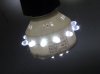
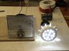
This is the improved version of the LED lamp posted about 1 year ago which ran on half wave rectified dc directly from the 240 Volts mains.
As I test my projects thoroughly and want to ensure a good reliability of the project a long time 2000 hours duration run is done prior to posting the details on the web.
Again, I have choosen for the resistive option because it is more reliable than a capacitor voltage dropper.
Parts required:
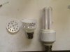
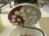
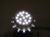
29 x White LED's
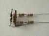
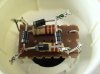
6 x 2k2 1Watt resistors
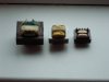
4 x 1N4007 diodes
small piece of vero board
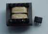
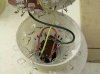
discarded CFL lamp base
Photo's attached with assembly details.
Calculations in part 2 of this thread.
As I test my projects thoroughly and want to ensure a good reliability of the project a long time 2000 hours duration run is done prior to posting the details on the web.
Again, I have choosen for the resistive option because it is more reliable than a capacitor voltage dropper.
Parts required:
29 x White LED's
6 x 2k2 1Watt resistors
4 x 1N4007 diodes
small piece of vero board
discarded CFL lamp base
Photo's attached with assembly details.
Calculations in part 2 of this thread.
")


")