Continue to Site

Welcome to our site!

Electro Tech is an online community (with over 170,000 members) who enjoy talking about and building electronic circuits, projects and gadgets. To participate you need to register. Registration is free. Click here to register now.

  • Welcome to our site! Electro Tech is an online community (with over 170,000 members) who enjoy talking about and building electronic circuits, projects and gadgets. To participate you need to register. Registration is free. Click here to register now.

5W voltage-controller LED Current Driver

Status
Not open for further replies.

JBrock

Member
Here is a voltage-controlled LED current driver for those who are not afraid to burn some POWER! Forget those wussy switching things trying to achieve, what?, 85% efficiency maybe? What a hassle.
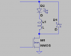
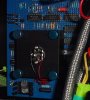
This driver is for a one-LED project. The LED is a 5-Watt royal-blue Luxeon Star. It cost $40 a couple years ago but you can get good Chinese counterfeits on eBay now for about ten. This device is a classified as a Class 2 laser - "Do not look directly at The Star!"
What can you do with one LED? The range of output is so great, that this LED is operated in analog mode. A voltage between 1 and 10 VDC is applied to the input of the driver to get a proportional percentage of The Star's output.
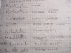
A controller generates eight different waveforms which run continuously. Lines from a pseudo-random linear feedback shift register choose which waveform is selected by the 4051 analog switch.
The current waveforms are shown, but their schematics are not revealed - yet. Only a hint - the waveforms are all generated using only 555 timers, 324 op-amps, or 3900 Norton amplifiers. I would like to see some good guesses as to how these waveforms may have been generated. If the results are worthy, I will post the solutions that were actually built and used to animate The Star of Captain Brock's BlueLight Box.
 

Attachments

  • Current Driver.JPG
    Current Driver.JPG
    246.8 KB · Views: 2,839
  • Star Current Waveforms.JPG
    Star Current Waveforms.JPG
    330 KB · Views: 1,846
  • BlueLight Star.jpg
    BlueLight Star.jpg
    78.9 KB · Views: 1,562
Last edited:
It looks to me like they were generated by the pencil and paper method. No need for a circuit then.You can make it anything you like.
What is the purpose of this device ?
Could I use it to warn incoming cars that I have cattle on the road ahead?
Could I drive say six of them to do the same?
What would you like me to guess at in a little more detail if you will?
 
You can build an 85% efficient SMPs with the same amount of parts.
 
It looks to me like they were generated by the pencil and paper method. No need for a circuit then.You can make it anything you like.
:DThe circuit is built and tested, as shown in the third picture, and as required by the rules of this forum!

What is the purpose of this device ?
:DThe purpose is to control current through the massive 5-Watt royal blue Luxeon Star LED in linear mode in response to the voltage waveforms. (Read original post again.)

Could I use it to warn incoming cars that I have cattle on the road ahead?
:D No. Get a MagLite with an LED upgrade.

Could I drive say six of them to do the same?
:D At 5 amp collector current rating, the TIP31 would be marginal. Get a nice beefy TIP3055 in a TO-247 case. The transistor is also operating in linear mode. But behold The Star! There is no need!

What would you like me to guess at in a little more detail if you will?
:D As stated, How might one generate the eight voltage control patterns graphed on page 2? I used 14 IC's to come up with all eight waveforms even though many share the same oscillators. Surely someone can do better. (No fair using microcontrollers!)

You can build an 85% efficient SMPs with the same amount of parts.
:D That is interesting. This controller can go from a few milliamps to 750mA. Does your switchmode have that kind of range? Remember, this is a voltage-controlled CURRENT regulator. Please share. I could be convinced.
 
:D That is interesting. This controller can go from a few milliamps to 750mA. Does your switchmode have that kind of range? Remember, this is a voltage-controlled CURRENT regulator. Please share. I could be convinced.

It's pretty simple, all you need is a comparator and a transistor (or a couple of transistors at most).

Read the following threads.

https://www.electro-tech-online.com/threads/high-power-led-controller.95832/
https://www.electro-tech-online.com/threads/led-switching-regulator.41375/
 
Just following on

:DThe circuit is built and tested, as shown in the third picture, and as required by the rules of this forum!

Yes sir Mr Brock. I think I have it now . I did not follow your meaning before.


:D No. Get a MagLite with an LED upgrade.

In fact I have a need for something bright and flashing in the daylight to alert traffic . I have settled on very bright LEDs ,18 of them. This Maglite and upgrade LEDs though sound interesting .Perhaps you might elaborate ,by PM if you wish to preserve your thread

:D As stated, How might one generate the eight voltage control patterns graphed on page 2? I used 14 IC's to come up with all eight waveforms even though many share the same oscillators. Surely someone can do better. (No fair using microcontrollers!)

Well this one is beyond my ability outright. I would use a waveform generator but I think you have them built up on the board and running in a random pattern . The decaying pulse though would be a capacitor discharging I suppose . Square wave and pulse might be a couple of 555s output . Ive not really ever studied the others so I would have to leave it there. I'll watch with interest

Thanks anyway for posting .I didn't doubt you had built it , but I would like to see a video of what it does ?
 
Last edited:
Check Out MAX16823 and Others

Ty, your application is so simple, all you need is a 555 timer and go with current-limiting resistors. (Ya, Hero will scorn that.) I would like to know your LED selection. You probably want red or yellow. There are some monsters available now, up to 12 watts. You will need to have a heatsink.

The point of my circuit is to run across the entire range of current from nearly zero up to ~700mA, controlled in response to an analog voltage. The star already becomes very bright at a few milliamps.

Here's a great blog on driving LEDs:
**broken link removed**
Check out the milled circuit board!
 
Did you check out the threads I linked to?

A PWM 555 can also be configured as an unregulated SMPS, simply by adding an inductor, a Schottky diode and a power MOSFET.

I'll post a spreadsheet which calculates the component values if you're interested.
 

Attachments

  • open loop LED buck switch.PNG
    open loop LED buck switch.PNG
    6.5 KB · Views: 1,377
Last edited:
Pwm?

Hero, I am intrigued... Since the project is completed, I don't plan on making any changes, but I am theoretically interested in the idea.

What frequency are you suggesting for the PWM?

How linear would the response be for this circuit?

What is the control range? For the BlueLight Star application it would need to go from 6mA to 750mA. That is greater than 100:1.

How much current ripple could be expected through the LED? (Probably not an issue at switching frequency.)

What is the response time? (Only need about 1ms or less.)

Yes, I did read the references. Many of these circuits are not intended for voltage-controlled response. It would be easy to convert voltage to PWM to use your idea.

Thanks for the input. Nice to meet a switching guy! -Brock
 
What frequency are you suggesting for the PWM?
The frequency will depend on the inductor size and ripple current. Higher frequencies will give less ripple but higher switched losses and larger inductors will reduce the ripple but are larger more lossy and expensive.

How linear would the response be for this circuit?
The circuit I previously posted won't be perfect, as it's unregulated.

Some of the circuits discussed in the other threads are more linear.

Anyway, even if the controller were perfectly linear, I'm not convinced that the over all device would be because LEDs certainly aren't linear. The voltage drop increase with current so the power consumption and power output won't have a linear relationship to the current.

What is the control range? For the BlueLight Star application it would need to go from 6mA to 750mA. That is greater than 100:1.
The circuit previously posted can be controlled from 0mA to full power.

How much current ripple could be expected through the LED? (Probably not an issue at switching frequency.)
It's a trade off between inductor size and switching frequency, see above.

Ripple current isn't a problem with LEDs, providing the switching frequency is over about 500Hz.

What is the response time? (Only need about 1ms or less.)
That depends on the switching frequency.

Yes, I did read the references. Many of these circuits are not intended for voltage-controlled response. It would be easy to convert voltage to PWM to use your idea.
Many of them can easily be voltage controlled.

Here's an example:
led-mos-smps-gif.32061

Just vary the value of Vref to alter the current.

Vref can be a voltage reference, such as a zener, with a potential divider in the output.
 
Status
Not open for further replies.

Latest threads

New Articles From Microcontroller Tips

Back
Top