Dr_Doggy
Well-Known Member
Recently i purchased some TL499acp
https://www.ti.com/lit/ds/symlink/tl499a.pdf
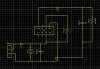
and most of the components listed on the datasheet, i am trying to boost a single AA battery, to run a micro-controller(16f526) and a RGB LED, so circuit is good, testing with pickit, circuit shuts down and led stops blinking below 3v (5v may be too much as i didnt load down my LEDS") 2.4-3.6videal
2.4-3.6videal
so. i will start from the begining:
according the datasheet i was to get a 50uH inductor, so i did test circuit with this one:
https://www.digikey.ca/product-detail/en/B78108S1473J/495-5568-1-ND/4245861
which obviously failed for obvious reasons, so i got some of these aswell:
https://www.digikey.ca/product-search/en?KeyWords=811-2046-ND &WT.z_header=search_go
that surprised me, i thought those would work forsure, but no, so next i tried this one:
https://www.digikey.ca/product-search/en/inductors-coils-chokes/fixed-inductors/196627?k=M8385-ND
and still nothing, so as always in these situations i did what i always do, started pulling resistors, first with pin4 resistor, then pin2 and pulled it to ground.
what i noticed is then is that i was actually using a 1.2v battery, so i switched it up to a 1.5v battery, and i $hit you not that the volts pulled up to stable 4v, powered down and up ideally several tests, and ran blinky program for 48hrs, again no resistors, on huge coil, at that point the battery died, and when i switched it out converter did not come back online. Its been said that im under volting it, so maybe i had a freak battery, either way i need resolution, should i really switch to oscillator circuit, i usually dont have much success,, I am experienced with multi-vibrator, and thinking about using that to drive boost switches.. here is block diag of what i'm dealing with:
2.5v SOLAR CELL ---DIODE --- AA BATTERY ---- app
2.5v SOLAR CELL ---DIODE --- AA BATTERY --boost conv-- 3.5v MICRO
need suggestion, cannot modify/stack solar cell, what is "Best" (easiest -- cost effective), adjustments i need to make here?
https://www.ti.com/lit/ds/symlink/tl499a.pdf
and most of the components listed on the datasheet, i am trying to boost a single AA battery, to run a micro-controller(16f526) and a RGB LED, so circuit is good, testing with pickit, circuit shuts down and led stops blinking below 3v (5v may be too much as i didnt load down my LEDS
2.4-3.6videalso. i will start from the begining:
according the datasheet i was to get a 50uH inductor, so i did test circuit with this one:
https://www.digikey.ca/product-detail/en/B78108S1473J/495-5568-1-ND/4245861
which obviously failed for obvious reasons, so i got some of these aswell:
https://www.digikey.ca/product-search/en?KeyWords=811-2046-ND &WT.z_header=search_go
that surprised me, i thought those would work forsure, but no, so next i tried this one:
https://www.digikey.ca/product-search/en/inductors-coils-chokes/fixed-inductors/196627?k=M8385-ND
and still nothing, so as always in these situations i did what i always do, started pulling resistors, first with pin4 resistor, then pin2 and pulled it to ground.
what i noticed is then is that i was actually using a 1.2v battery, so i switched it up to a 1.5v battery, and i $hit you not that the volts pulled up to stable 4v, powered down and up ideally several tests, and ran blinky program for 48hrs, again no resistors, on huge coil, at that point the battery died, and when i switched it out converter did not come back online. Its been said that im under volting it, so maybe i had a freak battery, either way i need resolution, should i really switch to oscillator circuit, i usually dont have much success,, I am experienced with multi-vibrator, and thinking about using that to drive boost switches.. here is block diag of what i'm dealing with:
2.5v SOLAR CELL ---DIODE --- AA BATTERY ---- app
2.5v SOLAR CELL ---DIODE --- AA BATTERY --boost conv-- 3.5v MICRO
need suggestion, cannot modify/stack solar cell, what is "Best" (easiest -- cost effective), adjustments i need to make here?