Continue to Site

Welcome to our site!

Electro Tech is an online community (with over 170,000 members) who enjoy talking about and building electronic circuits, projects and gadgets. To participate you need to register. Registration is free. Click here to register now.

  • Welcome to our site! Electro Tech is an online community (with over 170,000 members) who enjoy talking about and building electronic circuits, projects and gadgets. To participate you need to register. Registration is free. Click here to register now.

Searching for Synchronous Buck converter NFETs?

Flyback

Well-Known Member
Hi, does anyone know if there is a way to find NFETs for Synchronous Bucks?...How to search them?....As you know, a NFET for a Sync Buck must have Cgd at least 100 times less than Cgs. There is no way to search based on Cgd or Cgd/Cgs.
We need them for 17-32VIN, 13V5 OUT, 30A out, and for 17-58Vin, 13v5 out and 50A out.
We also need 4V5 gate drive.

Also, do you know if 4v5 NFETs are more likely to have CGS/CGD >100.

Also, synch FETs for synch Bucks need searching for based on trr and vf of their intrinsic diode...do you know how to search these out when no search engine refers to these parameters?

Also, for SMD FETs below 100V, which is the footprint that fits most of the other FETs aswell.?....there are so many , eg PowerDI5X6, PowerPak, Power-SO8 etc etc etc....its a myriad of confusion...which footprint (s) fit many of the other footprints too?
 
Last edited:
Its so you dont get spurious on-turning when the opposite fets turns on...there are many app notes on it on the www.
ti.com even used to make a synch buck fet pair to counter the issue.
Its Qgd/Qgs <1 and Cgd/Cgs <1/100
 
Last edited:
Its so you dont get spurious on-turning when the opposite fets turns on...
I thought the way you do that is to allow for deadtime in the switching waveforms and put a Schottky in parallel with the body diode for the "OFF" FET.

As far as finding a device you need to develop relationships with FAEs that work for manufacturers and distributors. Please tell me you have established those contacts.

It seems like datasheets from IR don't have explicit values for those parameters but rather one or more graphs that show a variation of related quantities, Ciss, Coss, and Crss with respect to Vds.

1712950542539.png
 
Last edited:
Thanks, so anyway, for Sync Buck Bottom FET, Cgd must be << Cgs. But as we know, if the d(Vgd/dt) is high then Cgd appears to be higher since Cgd(apparent) = i.(d(Vgd)/dt). So yes, its not just Cgd that we must look at...but Qgd. And we must review Qgd at the actual Vin. The higher that the Buck's Vin is...the lower must be the ratio of Cgd/Cgs.
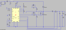
In the attached sim we see how the ringed capacitor being lower reduces the spurious turn-on of the low side FET.

And of course, tying in with the top post......Logic level FETs are much more susceptible to this spurious turn-on, simply because their Vgs(th) is so much lower. And when logic level FETs are used in Synch Bucks with Vin's > 30v, then things just get worse and worse.

Basically if you are doing a Synch Buck with Vin > 30V, then you really want to be throwing logic level FETs into the Bin. They are way to
susceptible to spurious turn ON when the top side FET turns ON.

Also, its noteable that Qgd/Qgs must be <1, though during spurious turn on in sync bucks, the lower FET actually has its gate shorted to ground by the driver, (and via any series resistance which would be low value)....so in fact, it makes you wonder why "Qgd/Qgs < 1" really applies in real life?
 

Attachments

  • LTC3891_SINGLE.asc
    6.4 KB · Views: 17
  • Synch Buck CGD.png
    Synch Buck CGD.png
    54.6 KB · Views: 20
Last edited:
For that level of power, you will probably need a dual phase solution. Look at the LTC3890, not the LTC3891. The low side FET needs to have low RDSON only, not low QG. The high side FET needs to have a good balance between low QG and low RDSON. These 2 characteristics are normally mutually exclusive, so a low RDSON FET will have a high QG. Look for a FET with a good Figure of Merit (FOM) for the high side FET as this represents a good trade off between QG and RDSON.

For the low side FET, a low RDSON means a high QG and this high input capacitance (which is similar to QG) will help to reduce the feedthrough that comes back at the Gate drive (via the Miller capacitance) when the switch node flies positive.

A parallel Shottkey diode across the will help reduce the current injection into the body diode that happens during the dead time between the FETs switching.

So... go onto Vishay's website and download all NFETs. Delete the ones that are too low in voltage and current. Construct a column called FOM which is QG * RDSON. Sort the FOM column and pick the FET with the lowest FOM. This is your high side FET.

Then sort the NFETs by RDSON. Pick the one with the lowest RDSON. This is your low side FET

The ideal package is one with no leads, so the PowerPAK SO8 is a good one.

Simulate. If the FETs heat up too much, move from the 3891 to the 3890 and design a dual phase solution.
 

Latest threads

New Articles From Microcontroller Tips

Back
Top