Continue to Site

Welcome to our site!

Electro Tech is an online community (with over 170,000 members) who enjoy talking about and building electronic circuits, projects and gadgets. To participate you need to register. Registration is free. Click here to register now.

  • Welcome to our site! Electro Tech is an online community (with over 170,000 members) who enjoy talking about and building electronic circuits, projects and gadgets. To participate you need to register. Registration is free. Click here to register now.

1 NAND Gate to trigger & reset 555

Status
Not open for further replies.

ThomsCircuit

Well-Known Member
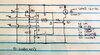
Sometimes I forget to turn off the 12v led lights in my closet so I'd like to activate this relay through a 555 and apply a delayed off of about 10-15 minutes so the relay is automatically disengaged if I forget to turn off the light.

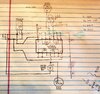
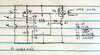
I altered this circuit so it connects to the circuit I have created.

Pin 2 of the 555 is triggered from the 4093 NAND gate. I would connect pin 2 to the output of the gate that connects to the speaker. I would connect pin 4 to the output from the touch pad. I understand output connected to the speakers (-) lead is held high until the touch sensor is pressed. It then drops to 0v causing the speaker to sound for 750ms which is controlled by C1 & R1. And the constant 5v from the touch pad will satisfy the 555 so it functions. Im hoping that is what is necessary to start the 555.
When the touch pad is pressed a second time the 5v from the touch pad is brought to 0v causing the 555 to reset. From what I understand pin 4 must have current to function so the 750ms pulse coming from the gate to pin 2 would be ignored.

So would this work correctly? If not can you help me configure this properly?
Thank you in advance.
 

Attachments

  • 20200414_145309.jpg
    20200414_145309.jpg
    3.6 MB · Views: 232
  • 20200415_072002.jpg
    20200415_072002.jpg
    4.6 MB · Views: 219
Just a quick comment about D1 in the 555 circuit, the way it is right now the relay will never activate. You need to put the diode across the coil (in parallel) not in line with it (in series).
 
A CD4093 can source or sink only a few mA, so is unlikely to be able to drive the LED or piezo sounder adequately. Buffer transistors are advisable/necessary.
 
Just a quick comment about D1 in the 555 circuit, the way it is right now the relay will never activate. You need to put the diode across the coil (in parallel) not in line with it (in series).
I will adjust the placement of the diode. Thank you so much.
 
A CD4093 can source or sink only a few mA, so is unlikely to be able to drive the LED or piezo sounder adequately. Buffer transistors are advisable/necessary.
I can do that. I currently have this on a breadboard using a different NAND and it lights up the led and sounds the peizo. I admit it is not as loud as it can be. It's a 5v speaker and getting 4v but it's ok for me.
 
Looks as though it'd work, you'd have to try it to be certain, lash it up on breadboard.
The 555 in monostable mode triggers when pin pin is less than 1/3 Vcc, if its held less than 1/3 Vcc it will stay triggered ie not time out.
Doesnt matter in your circuit as the 555 period is way longer than the piezo buzzer period.
That's reassuring to hear. I've got to order a few transistors and a few more relays but I am pleased. Thank you
 
I'm sure with a bit of jiggery pokery that could be done all in the nand chip, I see your using the gates doubled up.
However if thats what you have by all means go with it.
Makes a change these days not to have a microprocessor.
 
I'm sure with a bit of jiggery pokery that could be done all in the nand chip, I see your using the gates doubled up.
However if thats what you have by all means go with it.
Makes a change these days not to have a microprocessor.
Well I'm a do it your selfie and I certainly understand jiggery pokery. A user at another site helped me with the NAND but I do understand it better now. And yes I do have these 555's and I thought I'd put them to good use. I just wanted to be sure applying a pulse to pin 2 and vcc to pin 4 at relatively the same time was good practice or should I try to delay the trigger a bit perhaps with a resistor. Anyhow like you said I'll try it and tweak it if needed.
 
An ordinary old 555 barely works when its supply is only 5V. Its output goes up to only +3.6V. The base of the weak little BC547 transistor will be +0.7V when turned on which calculates a base current of only 2.9mA, then the transistor collector current will be only 29mA or less which might not be enough to drive your relay. Why not replace the relay with a transistor or Mosfet?
 
An ordinary old 555 barely works when its supply is only 5V. Its output goes up to only +3.6V. The base of the weak little BC547 transistor will be +0.7V when turned on which calculates a base current of only 2.9mA, then the transistor collector current will be only 29mA or less which might not be enough to drive your relay. Why not replace the relay with a transistor or Mosfet?
Yes. My relay needs 70ma to trip. Anyway to increase that with the 5.5v I have ? A larger transistor? I want to keep the relay setup.
 
An ordinary old 555 barely works when its supply is only 5V. Its output goes up to only +3.6V. The base of the weak little BC547 transistor will be +0.7V when turned on which calculates a base current of only 2.9mA, then the transistor collector current will be only 29mA or less which might not be enough to drive your relay. Why not replace the relay with a transistor or Mosfet?
My supply voltage is 5.5 volts
I've read (but may have mis-understood) that connecting pins 2+6 together may increase the output. If I'm accurate can you help my re-write this 555 so it works? It may not be perfect but it is what I have. Thank you for understanding
 
Pin 2 is connected to pin 6 on a 555 so that it can oscillate. It has nothing to do with its low output voltage. A graph on the datasheet shows its output voltage dropping when loaded. Since your relay coil needs 70mA then ANY transistor needs a base current of 7mA. Then the output voltage of the 555 will be your 5.5V-1.4V= 4.1V and the base resistor will have 3.4V across it and 3.4V/7mA= 485 ohms which is not available, use 470 ohms.
I hope your relay coil is 5V and not the 12V shown on your sketch.
Again, why use an old fashioned relay that wears out instead of a power transistor or Mosfet?
 

Attachments

  • LM555 output high voltage.PNG
    LM555 output high voltage.PNG
    19 KB · Views: 205
Pin 2 is connected to pin 6 on a 555 so that it can oscillate. It has nothing to do with its low output voltage. A graph on the datasheet shows its output voltage dropping when loaded. Since your relay coil needs 70mA then ANY transistor needs a base current of 7mA. Then the output voltage of the 555 will be your 5.5V-1.4V= 4.1V and the base resistor will have 3.4V across it and 3.4V/7mA= 485 ohms which is not available, use 470 ohms.
I hope your relay coil is 5V and not the 12V shown on your sketch.
Again, why use an old fashioned relay that wears out instead of a power transistor or Mosfet?
Ok. Thank you so much.
So I will change R2 from 1k ohm to 470 ohm
My 555 is an NE555 and yes the relay is 5v coil. The relay I'm using is good. I've used them for decades. If I had not already purchased them I'd be all up for a mosfet.
Thank you again
 
If the trigger is low after the reset goes high then it'll work, the only time it wouldnt work is if the trigger was high before reset went high.

Did someone say you need the diode across the relay coil with the cathode to + ?
 
If the trigger is low after the reset goes high then it'll work, the only time it wouldnt work is if the trigger was high before reset went high.

Did someone say you need the diode across the relay coil with the cathode to + ?
Pins 2 and 4 are supplied their respective currents at the same time from the NAND gate.
Working:
When the touch pad is pressed its center pin goes high (4.5v) and hits the NAND gates inputs, the leds blue pin and the pin 4 on the 555. My knowledge in electronics is poor but as it was explained to me the output that is connected to the peizo is high until the touch pads pin goes high then it goes low and sounds the buzzer. That output is also sent to pin 2 of the 555 which (on paper) should start the 555's cycle. Pressing the touch pad again reverses the state of the two outputs which should reset the timer.

Yes, I have placed the diode in the correct place on the 555 circuit. I uploaded here in a previous thread.

Audioguru was also helpful in changing the resistor R2 on the 555 circuit from 1K ohm to 470 ohm in order to drive the milliamps up so the 5v relays coil would engage.
 
Try it and see, if theres a problem with logic levels you could use one of the nand gates to invert the signal, I assume the gates are in parallel to increase current capability, if you reduced the current to the led you'd probably get away with one gate.
 
Status
Not open for further replies.

Latest threads

Back
Top