Continue to Site

Welcome to our site!

Electro Tech is an online community (with over 170,000 members) who enjoy talking about and building electronic circuits, projects and gadgets. To participate you need to register. Registration is free. Click here to register now.

  • Welcome to our site! Electro Tech is an online community (with over 170,000 members) who enjoy talking about and building electronic circuits, projects and gadgets. To participate you need to register. Registration is free. Click here to register now.

Relays and Microcontroller reset issue

Status
Not open for further replies.

lorenzoarce

New Member
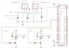
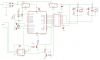
We have a board, which is powerd by an AC/DC converter of 12V and 2A. In the board there is a 5V regulator (LM1117-T-5.0) and another of 3.3V (LM1117-T-3.3). The 3.3V one is powered by the 5V one. The 3.3V regulator powers a MSP430F149 microcontroller. The 5V regulator powers the coils of 2 relays controlled by 2 relay drivers. These are made up of a transistor in cutoff/saturation which controlles the current throught the coil. Each driver is controlled by a digital output of the microcontroller.
The issue we have detected is that, sometimes, when we change the state of the drivers, the microcontroller resets. I guess it is a power problem, but I would appreciate any idea about what is happening there. I would thank you for any advise about what test I can do.
Thanks in advance. A simplified schematic is attached.
 

Attachments

  • Esquema.JPG
    Esquema.JPG
    57.4 KB · Views: 1,103
Yes, it is a simplified schematic. You need to be looking at the part you didn't attach.

The problem often lies:
1) bypass of power/ground of the microcontroller.
2) power/ground planes
3) circuit toplogy of reset and interrupt lines
4) what is attached to the relay contacts
5) I/O routines that cause stack overflow (yes it happens)
 
RE:

Thanks mneary for your quick answer. I will comment your answer:

1) bypass of power/ground of the microcontroller.

In theory this issue is already solved. I have bypass capacitors near the power line of the microcontroller.
2) power/ground planes
I guess you mention this in relation with the current flow and where it goes through. It should be also solved because I have used a big ground plane and power lines with appropiate width. However, I will take a look at the way the current should go, just in case. Thank you very much.
3) circuit toplogy of reset and interrupt lines
In theory the reset circuit is issolated with the relay drivers and contacts. I don't think this could influence.
4) what is attached to the relay contacts
2 motors are attached to the contacts. Their consumed power is around 30W and the power supported by the relay is much higher.
5) I/O routines that cause stack overflow (yes it happens).
The routines have been previusly used in 1 only relay circuits. I don't think this is a software issue. However, I would take a look at the routine.

The next thing I will prove is to issolate the power of the relays and the microcontroller. I will power the micro with a 3.3V power supply and lets see what happends. Just to prove if it is a power issue.
Thank you very much again. I will keep you informed about my steps. I would also appreciate more ideas.
 
I was having some trouble on a similar basis last year.The main issue causing this was the switching noise generated from the relay.
I used a RC snubber at the relay contacts and my resetting was circumvented
 
Thanks mneary for your quick answer. I will comment your answer:

1) bypass of power/ground of the microcontroller.

In theory this issue is already solved. I have bypass capacitors near the power line of the microcontroller.
The circuit you posted does not show any ceramic bypass capacitors, only electros.

Electrolytics have a relatively high impedance at high frequencies so you also need ceramic caps of 100 nF across the supply lines.

The high current and logic ground plans should be isolated from each other and only connected at one point.
 
Last edited:
Hi,
I had the similar problem of the above scenario of getting affected by the relay switching.
When the relay is off is may affect others channels. Only during off this will happen. I do not have any scope to monitor the supply lin eif it drops below certain level that cause the Pic to reset. I built several others similar board and link via RS485. The relay[off] action can cause some problem to others channel of the same device. And it happen to affect the next connected module as well. I share one 12Vdc adapter to 3 similar board with difference Address hardcoded into the Pic. The adapter rated at 12Vdc (regulated) 3.5A which I presume to be sufficient for three board. Each board had eight 12V G5LE relay (coil current 33.3mA).
I'm more suspicious about my hardware design rather then the coding that cause the problem.
LVP/Watchdog is disable in my programme.
Attached is the design i used. Would it be my design problem?
Regards
Alvin

p/s i had try using a snubber network [RC network] but this does not solve the problem. Even had MOV on the relay output, but the problem remain.
 

Attachments

  • rel8a_sch.png
    rel8a_sch.png
    13.5 KB · Views: 1,541
Hi,
I had the similar problem of the above scenario of getting affected by the relay switching.
When the relay is off is may affect others channels. Only during off this will happen. I do not have any scope to monitor the supply lin eif it drops below certain level that cause the Pic to reset. I built several others similar board and link via RS485. The relay[off] action can cause some problem to others channel of the same device. And it happen to affect the next connected module as well. I share one 12Vdc adapter to 3 similar board with difference Address hardcoded into the Pic. The adapter rated at 12Vdc (regulated) 3.5A which I presume to be sufficient for three board. Each board had eight 12V G5LE relay (coil current 33.3mA).
I'm more suspicious about my hardware design rather then the coding that cause the problem.
LVP/Watchdog is disable in my programme.
Attached is the design i used. Would it be my design problem?
Regards
Alvin

p/s i had try using a snubber network [RC network] but this does not solve the problem. Even had MOV on the relay output, but the problem remain.

The location of the snubbing diodes is important, they should be as close as possible to the coil, directly across the terminals if possible. A short trace or wire will act as a antenna even with the best diodes.

**broken link removed**
 
What are the values of the bypass capacitors C1, C2 & C4?

I would have used 100 nF ceramics and a 100 uF electro in parallel with C1 & C4
 
Last edited:
C1,C2 and C4 are 100nF ceremic diode and stay very very close to the chips as well.

As I wrote previously, you need electrolytic capacitors also.

I also noticed that there is no electrolytic at the output of the rectifier bridge.

So I suggest that you install a 470 uF (or greater) at the output of the rectifier bridge and a 100 uF inparallel with C1 & C4.
 
I had throughly tested the device without putting in the Ecap after the bridge rectifier. Have tested with some PLC lights and some halogen light. The relay module behave extremely fine. Really dun understand why? But when i installed these relay at site it seems resetting, when others channel are switch. Below is my configuration
Module A
ch1 3plc light
ch2 3plc light
ch3 3plc light
ch5 motorised1 screen up
ch6 motorised1 screen down
ch7 motorised2 screen up
ch8 motorised2 screen down

Module B and Mudule C are all with the similar setup. All 3 module is powered by a switched regulated 12Vdc 3.5A adapter
When one channel is switched, it will affect the others module to reset

I built another 3 similar module to test in myoffice to monitor if the device reset if some channel are trigger. I test with some load connected as well. But i only manage to setup 2 load on each module. Means i got total 6 light to control. All the testing went perfectly okay and it works very well. So i was so suspicious if my load is insufficient to cause the device to reset. Hence i built a comparator circuit, since i dun have a scope to monitor the 5V line on the microcontroller to check if it drops when the swicthing being done. The comparator circuit will monitor the 5V line and it will trigger the LED if it falls below 4.92V. After numerous test, the LED doesn't even lit up. Means the 5V does not even drop to this level. The comparator circuit had been tested and working fine.
What would be my problem with the microcontroller resetting. If i put up the Ecap of 1000uF 16V will it improve my device even further????
I dun have my choice left as i need all this module to get it working very soon. and no more resetting occur.
If the module is power by individual adapter would it be better????
Regards
Alvin
 
Alvin,
I found your post hard to understand.

If there is no Ecap after the rectifier bridge, you will have a full wave rectified waveform at the input to the voltage regulator.

Therefore, you're expecting the regulator to eliminate this very large ripple signal.

Is your comparitor circuit designed as a Flip Flop or just a comparitor?

If the latter is true, then the drop in voltage may be too brief for you to see the LED flash.
 
Last edited:
Alvin,
I found your post hard to understand.
>>sorry for my poor command in english. To simplify the setup, I had built 3pcs of 8
channel relay module. Excatly what I had installed at site. Module A, Module B and
Module C. All are link via Rs485 communication line. Each module is connected with 2
load. Which means i only use 2 relay channel for the trigerring. The purpose is to
monitor the switching, if it will affect the rest of the modules if Module A being
switched.
{first trial in my office without Ecap install after the bridge}
All the module works perfectly. While switching on and off any channel will not affect any micro to reset.
I really hope the resetting does occur so I can identify{simulate} the same problem at site.
{second trial in my office with Ecap 1000uF install}
Everything runs perfectly.


If there is no Ecap after the rectifier bridge, you will have a full wave rectified waveform at the input to the voltage regulator.
>>the purpose of using the recrifier is the prevent reverse polarity of the input voltage. However I'm using the 12Vdc 3.5A (very regulated DC voltage) adapter since it
had already rectified to a stable DC.

Therefore, you're expecting the regulator to eliminate this very large ripple signal.
>>i beliv there would not have any large ripple after the bridge as I'm using a regulated 12Vdc not 12Vac.

Is your comparator circuit designed as a Flip Flop or just a comparator?
>>it is design as a comparator with the Vref 4.92V. Building this comparator is to monitor the 5V line if it drops during the switching process. Since I do not have any
Scope to check on the 5V line.

If the latter is true, then the drop in voltage may be too brief for you to see the LED
flash.
>>I beliv so, maybe the triggering is too fast to lit up the LED. Therefore i had parallel another 100uF Ecap to the LED in order to charge the cap and discharge via the
LED. would this work?
 
>>I beliv so, maybe the triggering is too fast to lit up the LED. Therefore i had parallel another 100uF Ecap to the LED in order to charge the cap and discharge via the
LED. would this work?

No, the 100 uF would not have enough time to charge.

To light the LED to a short pulse, you need to drive the LED with either a monostable or a Flip Flop.

However, have you done what I suggested? That is - put an Ecap at the rectifer bridge and Ecaps in parallel with C1 & C4?
 
No, the 100 uF would not have enough time to charge.

To light the LED to a short pulse, you need to drive the LED with either a monostable or a Flip Flop.
>>noted, will try it tomorow.......hopefully had enough time to do the testing.

However, have you done what I suggested? That is - put an Ecap at the rectifer bridge and Ecaps in parallel with C1 & C4?
>>yes, everything is in place.
 
Maybe everything work so stable now. I doesn't find any fault [reseting ] take place.
Just worry the resetting will occur again.
 
help!!!

Hi there
is me again, the problem still persist for the microcontroller resetting issue. This device work quite perfectly fine if it is switching a low load. which i tested out with few flourescent light and a 500W halogen spotlight. When i install this device at site, the device will reset once in awhile, while i doing some switching process. Three pcs of a similar module was install with code A/B/C. They run on RS485 so only 1 comm cable is required. The reseting issue was not limitted to the switch device but it affect the neighbour device.
For eg.
if i command to switch device A, it will affect device B to reset or vice versa. This phonemena do happen quite frequently but not every switching will cause it to reset. Maybe a few trial of switching will cause others to reset. Even worst the switch device itself will reset.
Attach is the board i made. I had brieftly indicate the voltage drop on some essential point.
 

Attachments

  • IMAG0007a.jpg
    IMAG0007a.jpg
    261.5 KB · Views: 525
I suggest that you post a circuit diagram & a photo of the other side of the PCB.

Otherwise, we are working in the dark & can only guess what the problem may be.
 
Status
Not open for further replies.

Latest threads

New Articles From Microcontroller Tips

Back
Top