How are the untis powered?
Do they all share one power supply?
OR [no]
Does ech have its own supply?
yes, each using own 12Vdc adapter]
What type of power supply are you using? eg. a plug pack.
[regulated switching power adapter 12Vdc 3A - similar to notebook adapter]
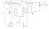
As I understand your problem, when a relay is operated or released on one unit it can cause a reset on another. [yes, it does happen, not every switch, but it does happen quite frequence]
Therefore, a transient pulse must be coming through thwe power supply or the data link. [i do not have the scope. it become quite difficult for me to troubleshoot the problem]
Have you tried disconnecting the dta link from one and see if it still resets when a relay is operated or released on another?[did not tried this]
Have you tried operating one unit from a 12 Volt battery in order to isolate it from the power supply? [it is isolated since i use one adapter for each module] This would prove whether the pulse is coming via the supply line. [hmmm......]
As emer dauz implied, you may need a low pass filter on the 12 Volt supply lines.