Electro Tech is an online community (with over 170,000 members) who enjoy talking about and building electronic circuits, projects and gadgets. To participate you need to register. Registration is free. Click here to register now.
Welcome to our site! Electro Tech is an online community (with over 170,000 members) who enjoy talking about and building electronic circuits, projects and gadgets. To participate you need to register. Registration is free. Click here to register now.
I have a led light strip I want to control with a pir sensor.
The strip runs on 5vdc at 300Ma.
The pir sensor will signal 3.3 volts out.
I have BD237 transistors that I could use if possible.
Thanks.
I was looking for a simple circuit like this one using a mosfet or power transistor.
The problem with this circuit is the 12 volts, it operates at 5vdc but goes off and stays off and won't retrigger.
Would an IRF 9540 operate at 5 volts?
I believe the 540 will only operate above 10vdc.
A 9540, P Channel, versus 540, n channel, are both a bit marginal, worst case spec, for turn on, 540 -
Then you have, as drawn, load is switched to supply, not to ground.
Start with 540, place load in drain.
+12 >> LED STRIP >> 540 DRAIN, 540 source to ground, 540 GATE to PIR.
If this is a one off look at 540 heat. To see if its on the marginal side, not turning on
hard enough with 3.3V. If a production item get a logic level MOSFET that will run off 3.3V
Is strip rating of 300 mA a hard limit or does strip have its own current regulated circuitry ?
If former you need to drop V to strip, use a zener, it wants to be (12V - 5V) = 7V. Its power
(50% margin) = 7V x .3A x 1.5 (margin) = > 3W, small heatsink on it. Note make these
calculations with worst case 12V value (high), same for Vz tolerance. So connections -
+12 >> ZENER >> LED STRIP >> 540 DRAIN, 540 source to ground, 540 GATE to PIR.
And fuse the the circuit.
Now not to confuse, if stirp is rated such that user must supply minimum 5V, with current regulated
to .3A, then a simple 3 terminal regulator, like LM317 operated in constant current mode
would be a clean easy solution to that problem.
Input diode for reverse polarity input connection. Not needed if you dont have that as a
potential issue.
So connections would be
+12 >> LM317 Input >> LEM317 Output >> R1 >> LED Strip >> 540 DRAIN, 540 source to ground, 540 GATE to PIR.
And the connection of LM317 ref pin to right side of R1.
Hi Dana;
Thanks for taking the time and making the effort to help with this.
I haven't studied it completely but I will.
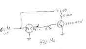
I managed to get it working just now using a 2222 transistor.
Hi Dana;
Thanks for taking the time and making the effort to help with this.
I haven't studied it completely but I will.
I managed to get it working just now using a 2222 transistor.
If using 6V, and switch hard on, you would get ~ 6V/5 ohms = 1.2A. But
I think you are not driving 2N2222 base hard enough. "Normally" one
uses a rule of thumb to saturate a transistor Ib = Ic /10.
Rb then = (3.3V - Vbe) / ( 300 mA / 10) = ~ 2.6 / .03 ~= 86 ohms.
But can the SR501 drive 30 mA at ~ 3.3V, I doubt it. Reason MOSFET better
choice.
Is your 2N2222 running hot, its Vce >> 200 mV, thats a sign its not saturated.
If you want only 300 mA thru LEDs then Rc = (6V - Vcesat) / .3 A ~= (6 - .2V) / .3
~= 20 Ohms.
Yes, the 2222 is running hot.
The current is less than what I had put on the diagram because my meter wasn't zeroed.
I'm trying to raise the current so the led will be brighter so a MOSFET would be better.
I raised the voltage to compensate for the PIR.
The current is only 1 mA as is, I 'll have to raise it to get more brightness from the light.
Disregarding the actual transistor, your base resistor is FAR too high to switch it ON properly - but the actual current capability depends entirely on the output stage of the PIR module.
I'd suggest trying 100 ohm instead of 4.7K, and see how that works - and measure the voltage either end of it when the LED is switched ON.
Any sort of switch like this, where it needs to pass a fairly high current, wants as much base current shoving down it as you can get - the 100 ohm (or even 82 ohms) is aiming around 30mA, which is the usual sort of maximum pin current for a PIC.
The 100 ohm resistor makes a difference in brightness, the + side at the led is now 275mA and 280 on the - side both measurements taken at the led strip.
There are limits to how much base current you can drive into a transistor without
damaging it or degrading its gain. As you can see by the graph below up to
a point you can lower the Vce (making it a better switch) , then additional base
current is simply wasting power. Your not in danger on this design as I think the
micro used in the sensor is limited to how much current it can provide out its
GPIO pin. Crazy thing is often in datasheets there is no max Ibase ratings for
bipolars, which is dumb.
You are striving to lower Vce to minimize power transistor dissipates, and
insure it functions as a switch as close as possible, eg. low V drop.
And another consideration is micros have limited pin current limits allowed,
to insure internal supply busses do not have their operating V compromised.
You can get some crazy operational behaviour in parts when their busses are
out of spec or marginal. Usually the current limnit is total current for all pins
in that GPIO port, but sometimes individual pins also have a limit. Ugly to debug
these kinds of issues.
I am supplying this for your knowledge base in future designs. To store in
your noodle
Well it works and the brightness is good.
The transistor is hot at 60 C so I'll try and replace that with a MOSSFET and step it down with a zenor diode.
I bought this light because it fits in a corner but it was false triggering with the pir that was installed on it.
It had two 10 ohm SMD resistors that were really hot, not sure if that was causing the false triggering.
Thanks for the help with this, couldn't have done it without you and I managed to learn something in the process.
3.3V logic level capable MOSFET is answer as that module, w/o any data on limits, capabilities, is
asking for trouble trying to generate enough base drive.
Note, because MOSFETs have such large C, to prevent overload on sensor internal busses when
that C is getting charged, use a gate R to limit surge current.
Yes, as I feared, the sensor isn't capable of supplying much current - that's less than 2mA.
By using a small NPN transistor, and a larger PNP transistor, you could switch the top side of the LED instead of the bottom, and overcome the lack of current from the PIR.
Check the 6th image in my hardware extras tutorial page:
This site uses cookies to help personalise content, tailor your experience and to keep you logged in if you register.
By continuing to use this site, you are consenting to our use of cookies.

")