Electro Tech is an online community (with over 170,000 members) who enjoy talking about and building electronic circuits, projects and gadgets. To participate you need to register. Registration is free. Click here to register now.
Welcome to our site! Electro Tech is an online community (with over 170,000 members) who enjoy talking about and building electronic circuits, projects and gadgets. To participate you need to register. Registration is free. Click here to register now.
I need to be sure I selected the right Re and Ce of my common emitters.
Here's what used:
IE = (VCC - VBE) / (RE + Rth)
where:
VCC is the collector supply voltage
VBE is the base-emitter junction voltage (around 0.7V for silicon transistors)
Rth is the Thevenin equivalent resistance seen from the base (including biasing resistors)
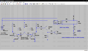
There is much wrong with that circuit, R6 shouldn't be there, and certainly won't be helping your problems - remove that and replace it with a piece of wire, and add a resistor feeding the base of Q3 (1K?). Plus remove the three spurious capacitors, C5, C6 and C7 - all those are doing is stopping your circuit working, I've no idea why you've just added random capacitors?.
Also Q1 and Q2 are likely to die from Vbe breakdown, as the supply voltage is too high - add diodes (1N4148 etc.) between base and emitter of each transistor, cathodes to bases, to prevent this.
I'm pretty dubious about the need for Q4 as well, and it could probably be replaced by a resistor - but with the suggested changes at least it has a chance to start to work.
I presume you haven't built this?, and are just playing with a simulator?.
I was writing something similar to what Nigel mentioned.
The circuit is flawed in so many aspects, that it would be FAR BETTER if the OP describes exactly what he is attempting to accomplish, rather than blindly attempting to make a flawed circuit to work, which may or may not solve his actual problem.
This is known as the XY Problem, and there is plenty of information on the web.
Have you done the urgent changes we've suggested?, it will be useless without them - the asc file above is of no use to me, post a schematic of the updated design, so we can check it.
When Q1 collector goes LOW that pulls current through R6 and the base of Q3, this turns Q3 hard ON, and the collector goes to 12V or so, the 12V goes through R7 to the base of Q5, turning that ON. R7 at 6809 ohms will give about 17mA base current of Q5, lower R7 if you want more current.
D1 and D2 are good, R5 isn't needed (and can only mess things up), replace it by a piece of wire, also R10 doesn't need to be as low as 470 ohm, stick 4.7K in it's place.
I would also suggest R1 and R2 are rather low at 180, for no purpose, but if you've got your frequency where you want it, then it's probably easier to leave them be?.
This site uses cookies to help personalise content, tailor your experience and to keep you logged in if you register.
By continuing to use this site, you are consenting to our use of cookies.