Electro Tech is an online community (with over 170,000 members) who enjoy talking about and building electronic circuits, projects and gadgets. To participate you need to register. Registration is free. Click here to register now.
Welcome to our site! Electro Tech is an online community (with over 170,000 members) who enjoy talking about and building electronic circuits, projects and gadgets. To participate you need to register. Registration is free. Click here to register now.
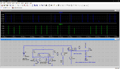
Do you realize that you don't have a spice model for Q5? I'm guessing you got that error message, and ignored it, so LTSpice uses a VERY basic model. This model has a beta of 100 at any collector current, and it has nothing to reduce switching speed; no capacitance, no storage time, no ft. Real high power bipolar transistors generally have very slow switching speeds. In effect, the generic model is a current-controlled switch. It does have a base-emitter diode, but that only serves to slightly reduce the base current.
I could not find a spice model for Q5 (FLJ9620). You could use a different transistor. In your simulation, the collector voltage is only reaching 50V, but I suspect it will go higher if you ever get it to work...
You can't damage a transistor in a simulation.
EDIT: Have you considered a MOSFET? Seems to me that would be a better choice.
Well, I feel a little stupid. That transistor works a lot better than I thought it would.
You could have saved my bruised ego if you had included that spice model when you posted the .asc file.
I am still learning about MOSFET's. I have got a MOSFET circuit I am working on, but that's another subject.
Don't let it sink you down. I was just being helpful.
If you find a use for the transistor, let us know.
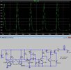
Your latest simulation in post #18 said you were getting "20KV 5mA 13KHz", but I ran the sim and got 1.3kV@323 kHz.
What's up with that?
I have made some mods, and currently have 9.5 kv p-p @20 kHz, but the pulse width is only about 2.2us.
Don't know if this is an improvement or not.
You didn't say "20KV 5mA 13KHz", but it was a comment on the schematic that you posted in #18.
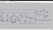
Please post MJE18004 spice model. Without it, your sim won't run.
Why does your power supply have 1.2 ohms series resistance?
Are the values of R8 and R9 set in stone, or can they change?
With 24kv, you can only get 12 ma through 2 Meg.
This site uses cookies to help personalise content, tailor your experience and to keep you logged in if you register.
By continuing to use this site, you are consenting to our use of cookies.