Well since this is my first post I guess I should do a short background. I'm just getting started in electronics and I think I may have found a new hobby. I decided to get into this with a project I saw online, an optical tachometer to get the headspeed of an rc helicopter. The creator did all the code in picbasic and it's all functioning properly. I will be doing future programming in C as I have a background in C++ and C-like scripting.
The problem I'm having with this project is the circuit. In the instructions it has a couple different circuits separated. I wanted to make this all on one board, but it isn't functioning properly.
Here is the project: **broken link removed**
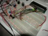
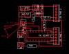
When I follow the instructions and lay it all out on the breadboard it all functions perfectly, however when I tried it on a pcb with the attached schematic I did it does not function properly.
The motor circuit functions as well as the IRLED and sensor. The problem is the LCD screen has one row of solid black squares and does not output anything other than that. I heard this is the "ready mode" of the LCD. So, somehow the LCD is not receiving data to display I guess. I compared the layout with the instructions on the site and all the connections seem right. Does anyone see anything that could cause this behavior? This thing is driving me crazy. I've been going over this time and time again for a week.
Thanks for any ideas, things to check, etc...
BTW, the LED, SEN, PWR are all 2 pin headers.
The problem I'm having with this project is the circuit. In the instructions it has a couple different circuits separated. I wanted to make this all on one board, but it isn't functioning properly.
Here is the project: **broken link removed**
When I follow the instructions and lay it all out on the breadboard it all functions perfectly, however when I tried it on a pcb with the attached schematic I did it does not function properly.
The motor circuit functions as well as the IRLED and sensor. The problem is the LCD screen has one row of solid black squares and does not output anything other than that. I heard this is the "ready mode" of the LCD. So, somehow the LCD is not receiving data to display I guess. I compared the layout with the instructions on the site and all the connections seem right. Does anyone see anything that could cause this behavior? This thing is driving me crazy. I've been going over this time and time again for a week.
Thanks for any ideas, things to check, etc...
BTW, the LED, SEN, PWR are all 2 pin headers.
Attachments
Last edited:
")