Continue to Site

Welcome to our site!

Electro Tech is an online community (with over 170,000 members) who enjoy talking about and building electronic circuits, projects and gadgets. To participate you need to register. Registration is free. Click here to register now.

  • Welcome to our site! Electro Tech is an online community (with over 170,000 members) who enjoy talking about and building electronic circuits, projects and gadgets. To participate you need to register. Registration is free. Click here to register now.

another FM transmitter project

Status
Not open for further replies.
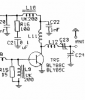
Once you said this RF amplifier has no gain. I simulated and got the waveform around mV peak to peak :) . I replced the collector 330R with little 100nH inductor and got very high amplitude (like mod4) at output. I think using inductor instead of resistor is much better. (but it produces lots of harmonics). LC performs very well here but here "inductor is better than resistor" isn't it?
 
Pre-amp of Mod-4 won't perform well without changing the bias at 9V. I want to use this preamp with pre-emphasis at another FM Tx which has no voltage regulator. So supply might be 5V, 6V, 8V or 9V according to my old batteries how much I can find :)
Are athere any simple idea to make able to work the preamp at 4V to 9V without regulator? Like....adding a resistor in the supply? May be hard to do. Zener comsumps more battery.
 
I made my Mod 4 by copying an FM transmitter that didn't work and I made 4 modifications to it:
1) Its preamp didn't work and the oscillator frequency changed when the 9V battery dropped below 7V. I added a low dropout 5V voltage regulator that still works when the 9V battery drops to 5.5V.
2) It sounded awful so I added pre-emphasis.
3) Its oscillator frequency changed when something moved towards or away from the antenna that was connected to the oscillator's tuned circuit. I added an RF amplifier between the oscillator and the antenna.
4) I can't remember the 4th mod.
 
I did little experiment with the pre-amp applying different voltages. Is it valid?

I found audio source (mV) is directly related to bias factor. Is it determined by a resistor for electret mic (gain controller)? Or by attenuator (audio to ground) resistor while injecting line out audio? I used 50mV to 9V. Check the amplitude, which is the best peak to peak and which level starts to distort audio?
 

Attachments

  • GV.GIF
    GV.GIF
    30.6 KB · Views: 232
=Willen;1118323]I did little experiment with the pre-amp applying different voltages. Is it valid?

I found audio source (mV) is directly related to bias factor. Is it determined by a resistor for electret mic (gain controller)? Or by attenuator (audio to ground) resistor while injecting line out audio? I used 50mV to 9V. Check the amplitude, which is the best peak to peak and which level starts to distort audio?
Pre-emphasis boosts high frequencies. Distortion is high frequencies so distortion is also boosted by pre-emphasis.
A transistor without negative feedback produced by an unbypassed emitter resistor has high distortion when its output voltage swing nears the positive supply. The voltage input change causes an exponential (instead of linear) voltage output change. Then a higher supply voltage allows the transistor to produce less distortion.

I never tried Collin's (Talking Electronics) very high value resistor to power an electret mic and attenuate it. Instead I use the datasheet value of 10k for a 9V supply so the current is the rated 0.5mA, the DC voltage is the correct at 5V and it is sensitive. I think Collin's very high value resistor causes distortion.

You do not want powering a mic to attenuate the signal because then the preamp must have extra voltage gain which also produces extra distortion.
Instead you want the mic preamp to amplify the low level from the mic with low distortion. The distortion Is less when the supply voltage is high.
 
Last edited:
Please rank these transistor from Good (average) to Best according to its spec for 100MHz application. (May be frequency, hFE and current is most responsible)

-BC549
Ic= 100mA (max)
TPD= 500mW (max)
hFE= 420-800mV
fT= 100MHz (min)

-BC337
Ic= 500mA (max)
TPD= 625mW (max)
hFE= 100-600mV
fT= 100MHz (min)

-BC547
Ic= 100mA (max)
TPD= 625mW (max)
hFE= 110-800mV
fT= 100MHz (min)

-2N2222
Ic= 800mA (max)
TPD= 500mW (max)
hFE= 30-300mV (?)
fT= 250MHz

Your ranking will teach me lot for choosing best transistor.
 
Last edited:
Please rank these transistor from Good (average) to Best according to its spec for 100MHz application. (May be frequency, hFE and current is most responsible).
The BC549 is a low noise audio transistor. The others are ordinary general purpose low power transistors.
All of then can oscillate at 90MHz and the 2N2222 can oscillate at maybe 200MHz (It is so old that I could not find a datasheet listing its fT, its minimum gain at 100MHz is only 2.5dB).

None of them is a good RF amplifier at 100MHz. I used the 2N3904 general purpose transistor that has an fT of 300MHz minimum and it works well in my low power transmitter.
 
2n2222 is so old that I could not find a datasheet listing its fT, its minimum gain at 100MHz is only 2.5dB. None of them is a good RF amplifier at 100MHz.

How you said exactly 2n2222 has 2.5dB at 100MHz? I cannot find exactly in datasheet, are there any graph of 'fT vs. gain'? Show me an example to find the gain at 100MHz of 2n3904 please!

I think gain is dependent also on type of amplifier. May be Class A has lower gain and Class C has higher gain.
 
Fairchild's datasheet of the 2N2222 is very old.
I like Fairchild's datasheet of the 2N3904 because it has a graph of typical input impedance at 1kHz and it has a graph of typical current gain in dB's at 100MHz.

I was wrong. The maximum current gain for the 2N2222 at 100MHz is 2.5 times, not 2.5dB.
2.5 times is about 8dB so the 2N3904 with a typical gain of 15dB is much better.

This is current gain, not voltage gain.
 

Attachments

  • 2N2222.png
    2N2222.png
    11.2 KB · Views: 226
  • 2N3904.png
    2N3904.png
    25.2 KB · Views: 222
No.
The high impedance collector of the RF transistor should have a pi filter (a C to ground, a series L and another C to ground) then connect the low impedance antenna.

Here are different types of impedance matching network than you said. Is it valid type of network or fault?
 

Attachments

  • Impedance network I.gif
    Impedance network I.gif
    10.5 KB · Views: 214
  • Impedance network II.png
    Impedance network II.png
    15.4 KB · Views: 218
The collector coil needs to have a parallel capacitor to tune it. Then harmonics are reduced and the collector voltage can swing to double the power supply voltage.

In Google, I searched for Antenna Matching Circuit Design and found an article that describes how to match a high power low impedance transmitter (10 ohms) to a 50 ohm antenna which is backwards for our little low power transmitters with a high impedance collector.
Then I found this one that shows how to design a pi network: https://en.wikipedia.org/wiki/Antenna_tuner#Classic_circuit
 
high power low impedance transmitter (10 ohms) to a 50 ohm antenna

Tuned LC has higher output impedance like 1K to 5K, Class C has low output impedance like 10 ohm?
 
Some high power transmitter outputs have a low impedance. High current equals low impedance.
Class-C has nothing to do with collector impedance.
 
I made various coils and looks so good like professional! And working nice too. But today I found a new term 'Pitch' on coil. Like this "10mm diameter, 5 turn, 4 pitch". Searched on google and saw, read few pictures and articles but couldn't understand what are they saying. Firstly i guessed pitch is 'gap or space between each turn' but i think articles says it is not actually. Can you elaborate the term Pitch?
 
I do not know the term called pitch on a coil. I make my coils with enamelled wire and the turns are tight together so they cannot move.
 
I found my Philips 1968 databook from when I worked at Philips.
Wow!!! You were working at Philips??? So exciting! I like to ask few question then-

How transistors are developed (Developing process) and how these can produced with same spec around world? Wow a semiconductor company!!?
 
Many companies get together to make the same transistors in case one company cannot make enough then the other companies can supply them.
The specifications and details about how they are made are shared.

It was interesting working for Philips. They made semiconductors, products, electric motors, speakers and many more things.
I saw and tested their very first cassette tape recorder/player (they invented the tape cassette) and LEDs.

On the production line a worker spotted two pieces of metal the same size. One had one hole and the other had two holes. When he made a suggestion to have both pieces made with two holes then the savings were rewarded to the worker.

I showed that a resistor was not needed in a car radio and I was rewarded a Philips shaver.

I bought a Philips color TV as my first one at an employees discount. It lasted 26 years and I modified it so it was extremely clear. Some of my modifications allowed it unscramble cable TV pay-per-view for free.

I worked for a year with Philips office computers when computers were very new. The logic was DTL, the RAM memory was core (many tiny ferrite donuts on many wires) and the program was fed in with punched cards. I fixed a problem by adding a new IC on top of an existing IC.
 
Status
Not open for further replies.

Latest threads

New Articles From Microcontroller Tips

Back
Top