Continue to Site

Welcome to our site!

Electro Tech is an online community (with over 170,000 members) who enjoy talking about and building electronic circuits, projects and gadgets. To participate you need to register. Registration is free. Click here to register now.

  • Welcome to our site! Electro Tech is an online community (with over 170,000 members) who enjoy talking about and building electronic circuits, projects and gadgets. To participate you need to register. Registration is free. Click here to register now.

A circuit to block back-feeding to another line

JaforSadik

New Member
Hello,
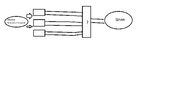
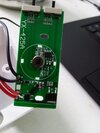
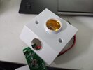
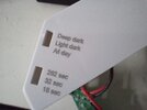
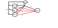
I have 3 Motion Sensors(Infrared Sensors) that work on 220V. I want to install these 3 sensors in 3 rooms and connect a single siren because thieves have recently cut the window bar and got inside my house.

The Problem.
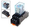
If I connect each of them and connect a single siren, if one gets triggered then it will send 220v down the line and other sensors that are connected are gonna get fried so I need help to build some sort of circuit that will just receive these 3 sensors' input and one gets triggered it will just send the power to the siren, not to the other lines. the sensor module and the siren work on 220 volts this is the voltage that my country uses. another note I am using the word circuit but I cannot get a circuit board custom-made in my country so if anyone can just tell me or draw me a diagram with the components that would be a very big help
 

Attachments

  • question.png
    question.png
    16.6 KB · Views: 42
The motion sensors probably won't be damaged.

If they are designed to operate 220 V lights, many motion sensors like that will be wired with a switch in parallel so that the light can be turned on without the motion sensor. I have two areas in my house that have lights operated with a motion sensor and switches to leave them on if I want.

When you have many motion sensor and one sensor turns on, the other motion sensors will be in exactly the same state as if a switch had turned on.

If you want to separate them all, just buy three mains-powered relays. Connect the three coils as the loads, one on each of the the motion sensors, and connect the relay contacts in parallel. It's a waste of effort as most motion sensors have relays built in to power the outputs.
Mine doesn't have the switch to use manually but I have attached the pictures of the sensor the button on the side is for choosing how long it will stay on and in which condition the sensor works, if you can tell me if I can just connect the neutral and phase of 3 sensor's in series and attach a siren.
 

Attachments

  • 1709783294764.jpg
    1709783294764.jpg
    117.1 KB · Views: 51
  • WhatsApp Image 2024-04-02 at 23.40.54_80f73ee2.jpg
    WhatsApp Image 2024-04-02 at 23.40.54_80f73ee2.jpg
    97.9 KB · Views: 48
  • WhatsApp Image 2024-04-02 at 23.40.54_c1f0e01f.jpg
    WhatsApp Image 2024-04-02 at 23.40.54_c1f0e01f.jpg
    167.3 KB · Views: 46
As I understand it, each sensor is powered continuously by 220 Vac, and each sensor switches its 220Vac to its output when tripped. yes / no - ?

If yes, this can be done with three relays. Low cost relay modules with screw-terminal connectors are available on ebay. No pc board, no soldering. Each sensor output powers one relay coil. All three relay NO contacts are wired in parallel to switch 220Vac to the siren.

ak
all I can find are 5vdc relays
 
all I can find are 5vdc relays
You're not looking very hard then, hundreds of different types of relays are available, many of them 220/240V AC. (just enter 'ac mains relay' in google.

However, your diagram in post #6 looks fine - just make sure that you get L1's and L2's the correct way round.

I'm presuming the little square 4 pin device is either an opto-triac, or it's a bridge rectifier and the large device to the right is an SCR. A picture of the other side of the board, so we can see the connections, would be helpful.
Here's the backside and i found this relay
 

Attachments

  • IMG_20240403_135640.jpg
    IMG_20240403_135640.jpg
    1.8 MB · Views: 42
  • IMG-20240403-WA0002.jpg
    IMG-20240403-WA0002.jpg
    45.5 KB · Views: 41
  • WhatsApp Image 2024-04-03 at 14.05.05_591f8870.jpg
    WhatsApp Image 2024-04-03 at 14.05.05_591f8870.jpg
    111.8 KB · Views: 34
The relay is not switching very much current, so its size is not important.

What is is the coil voltage rating. You want a relay with a 220 V coil, and contacts rated for 220 V. The number of contacts and the contact arrangement can be just about anything: SPST (NO), SPDT, DPST (NO), DPDT, etc.


ak
 
No, it should make no difference.
The relay is not switching very much current, so its size is not important.

What is is the coil voltage rating. You want a relay with a 220 V coil, and contacts rated for 220 V. The number of contacts and the contact arrangement can be just about anything: SPST (NO), SPDT, DPST (NO), DPDT, etc.


ak
so it worked, but now I have a completely different problem. whenever the electricity goes out and my generator kicks in or the power comes back on the alarm rings for 2.30 Seconds, I tested the individual sensors all of them behave the same way whenever it gets power after staying off it activates for 2.30 seconds. this has become really annoying to me and my neighbors, so how can I make a delay circuit that if it gets the power it would let the power through after a certain time ex 2\3 seconds
 
As in your other thread, you need a battery backup to keep it running - PIR sensors take a while to settle down when powered up, hence it triggers when the generator kicks in. A backup battery to prevent that will cure the issue.
 

Latest threads

New Articles From Microcontroller Tips

Back
Top